Vibration resistant camera for mounting to object

a technology for mounting cameras and objects, applied in the field of vibration-resistant cameras for mounting to objects, can solve problems such as damage to the camera itself, and achieve the effect of reducing the deleterious effects of vibrational disturbances

Inactive Publication Date: 2009-10-08
DIGITAL ALLY
View PDF5 Cites 44 Cited by
  • Summary
  • Abstract
  • Description
  • Claims
  • Application Information

AI Technical Summary

Benefits of technology

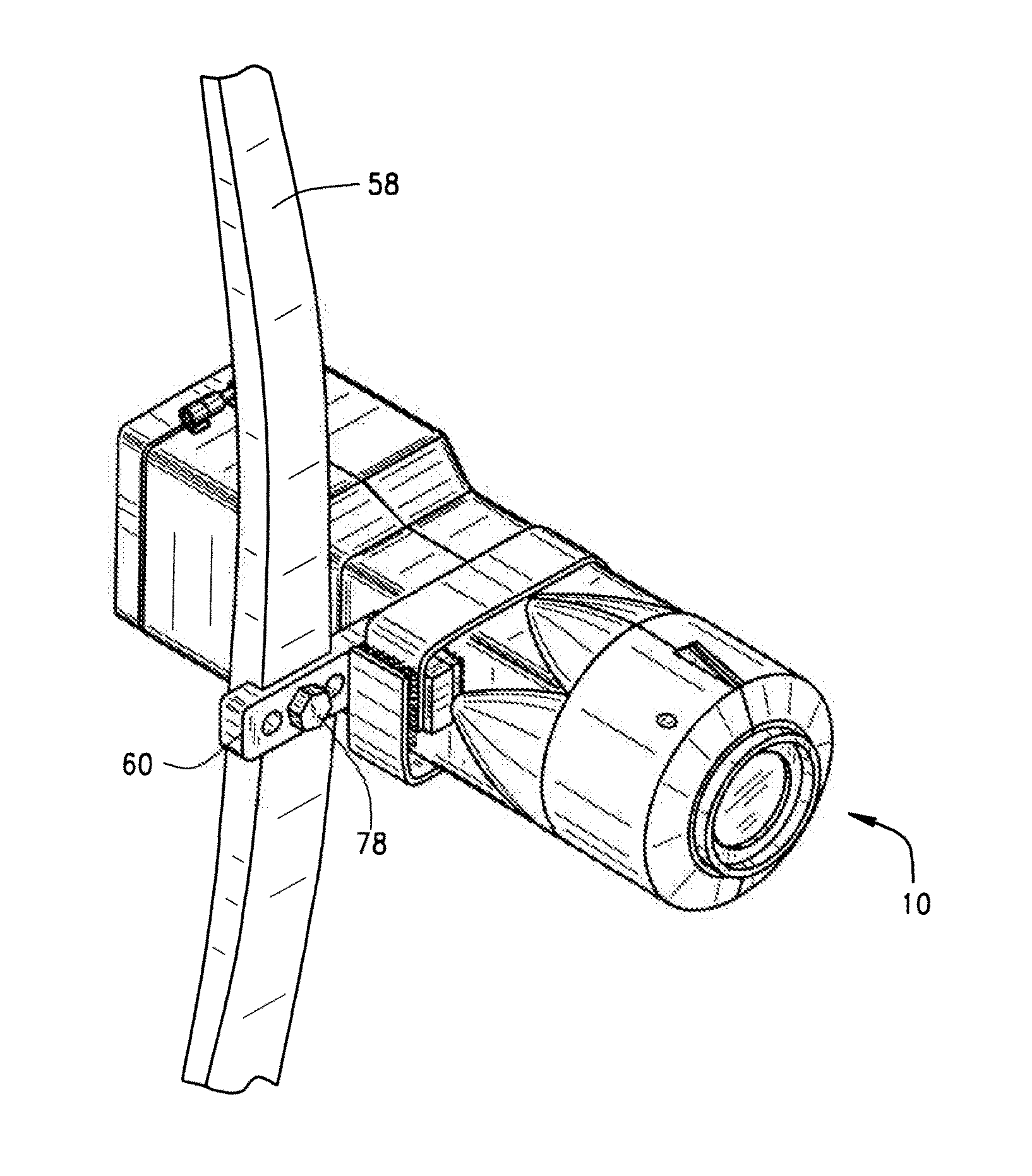
[0005]There is, therefore, provided in the practice of the invention a camera that is mountable to a bow. The camera is encased within a housing, which has a vibration-dampening member to decrease the deleterious effects of vibrational disturbances caused by the release of the bowstring. The camera can be either a single shot camera, or a video camera.

Problems solved by technology

The twang of the bowstring, besides creating a vibratory distortion to the recording process, is also a violent shaking that can cause damage to the camera itself.

Method used


Image

  • Vibration resistant camera for mounting to object
  • Vibration resistant camera for mounting to object
  • Vibration resistant camera for mounting to object

Examples


Embodiment Construction

[0028]The invention will now be described with reference to the drawing figures, in which like reference numerals refer to like parts throughout. For purposes of clarity in illustrating the characteristics of the present invention, proportional relationships of the elements have not necessarily been maintained in the Figures. Instead, the sizes of certain small components have been exaggerated for illustration.

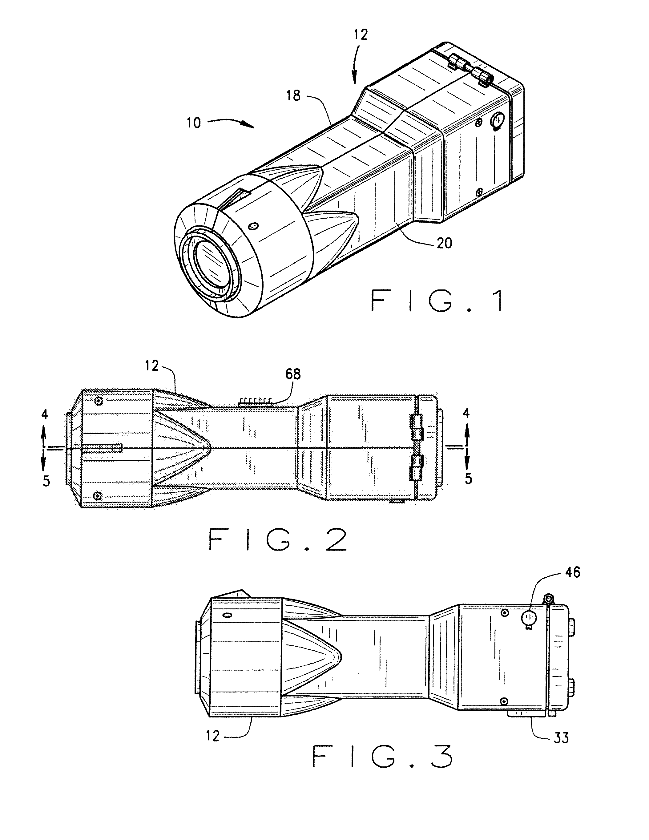
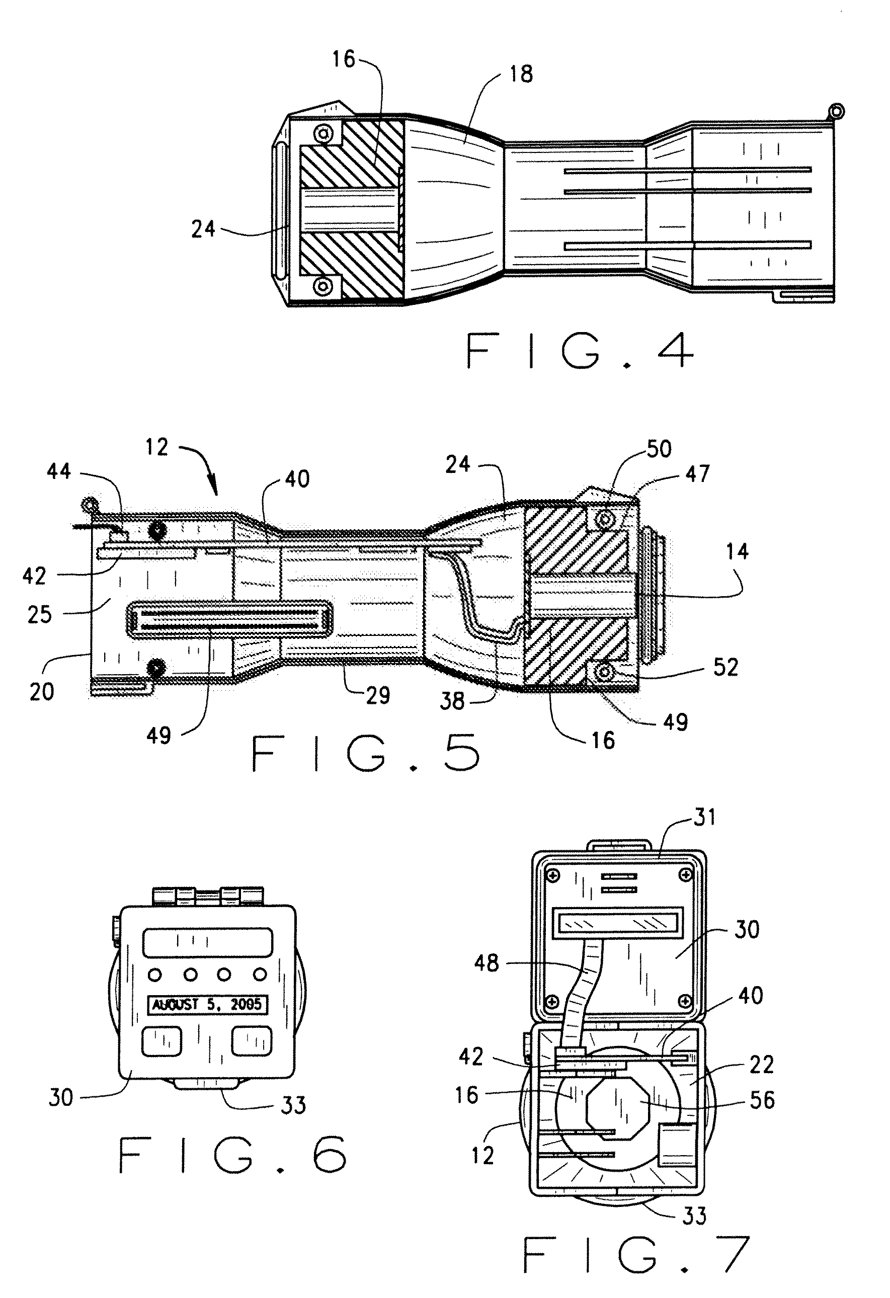
[0029]An embodiment of the present inventive bow camera apparatus is illustrated in FIG. 1 and is designated generally by the reference numeral 10. The apparatus comprises a housing 12, camera 14 and vibration-dampening member 16 as can best be seen in FIGS. 5 and 16. Housing 12 is comprised of a thermoplastic material, such as a polycarbonate / ABS alloy, or a light-weight metal alloy such as aluminum or magnesium. Housing 12 is comprised of right shell member 18 and left shell member 20 (from the perspective of one pointing the camera) which are adapted to be affixed together ...


PUM


Abstract

A digital camera is adapted for being mounted to a bow for archery. The camera comprises a self-contained digital unit within a housing and is protected from vibrational disturbances caused by the release of the bowstring. A viscoelastic material is used to reduce vibrations. The housing is water resistant to protect the internal circuitry of the camera from environmental elements encountered during hunting. A secure digital slot is connected to the digital camera circuitry and can accept a SD flash memory card. The camera may also be connected for transmitting images to an external device for viewing.

Description

CROSS REFERENCE TO RELATED APPLICATIONS[0001]This present continuation patent application claims priority benefit of an earlier-filed U.S. non-provisional patent application titled “Vibration Resistant Camera for Mounting to Archery Bow”, Ser. No. 11 / 198,247, filed Aug. 5, 2005, and of an even earlier-filed U.S. provisional patent application titled “Bow Camera”, Ser. No. 60 / 599,137, filed Aug. 5, 2004. The identified earlier-filed applications are hereby incorporated by reference into the present application.BACKGROUND OF THE INVENTION[0002]This invention relates to cameras mounted to archery bows. The thrill of the hunt, and head-to-head competition in archery contests, has motivated the archer to record his performance. The benefits of capturing the travel of the arrow, or reaction of the prey, are numerous and help the hunter / archer to enhance his skills. By watching the recorded activity, the hunter / archer can better understand the mechanics of the sport, and correct errors whe...

Claims


Application Information

Patent Timeline
Patent Type & Authority Applications(United States)
IPC IPC(8): G03B17/00
CPCG03B17/02G03B17/561G03B29/00
Inventor ROSS, JR., CHARLES ANDREWHALER, ROBERT DALE
Owner DIGITAL ALLY
Why Eureka
Try Eureka