Reformer for a fuel cell

Inactive Publication Date: 2009-10-08
EHNERDEJ GMBKH
View PDF7 Cites 6 Cited by
  • Summary
  • Abstract
  • Description
  • Claims
  • Application Information

AI Technical Summary

Benefits of technology

[0010]In one preferred embodiment, the chamber inlet is disposed near to a first axial end of a heat pipe and the chamber outlet near to a second axial end of the heat pipe so that the temperature can be compensated over as large as possible

Problems solved by technology

The reforming process is an endothermic reaction in which there is a pronounced drop in temperature, thus resulting in conversion losses.
In a CPOX reformer, the heat produced net in the inlet zone of the reformer is so high that damage to the materials involved may occur, for instance, the catalytic active medium may be deact

Method used


Image

  • Reformer for a fuel cell
  • Reformer for a fuel cell
  • Reformer for a fuel cell

Examples


Example

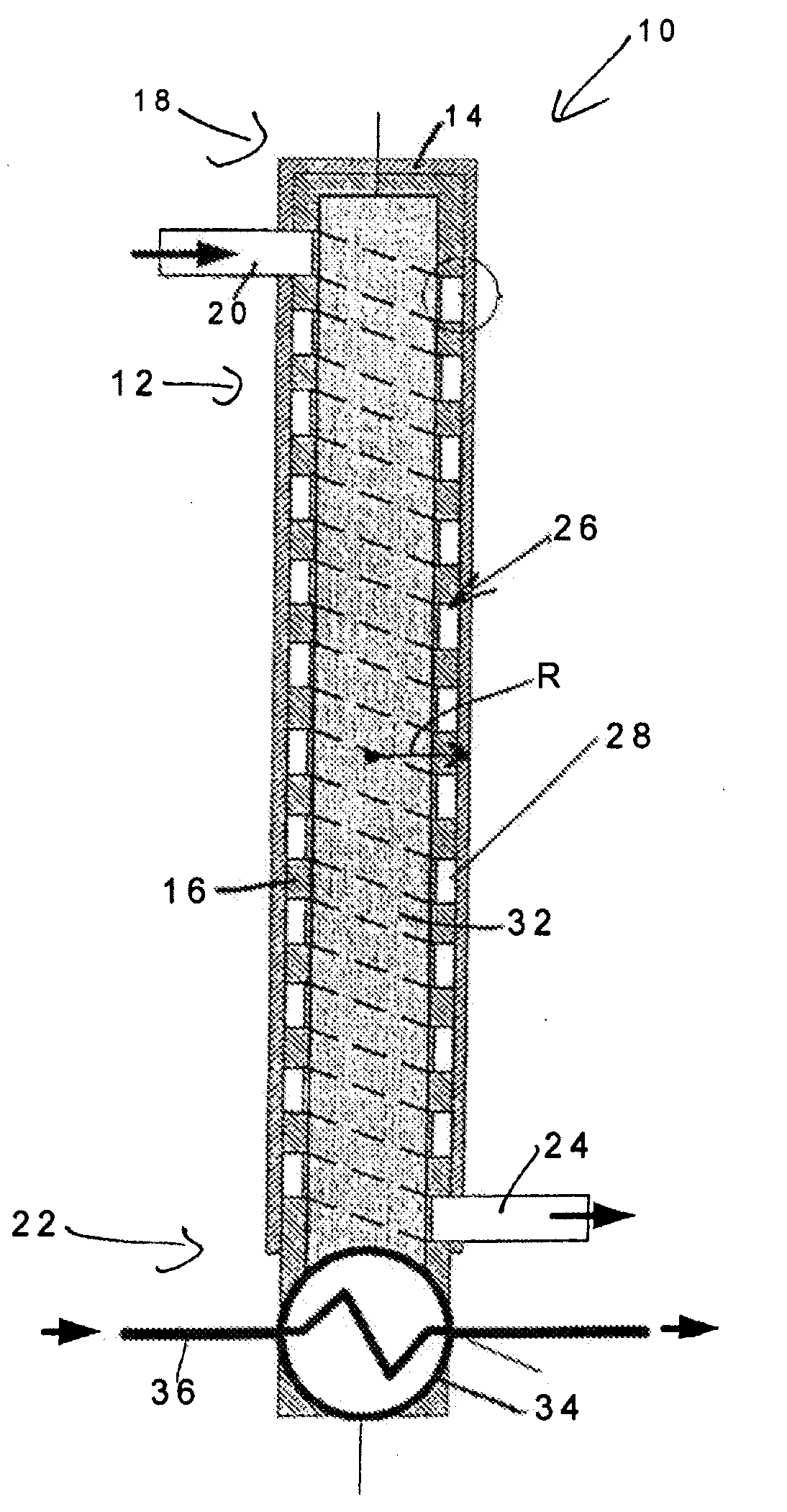
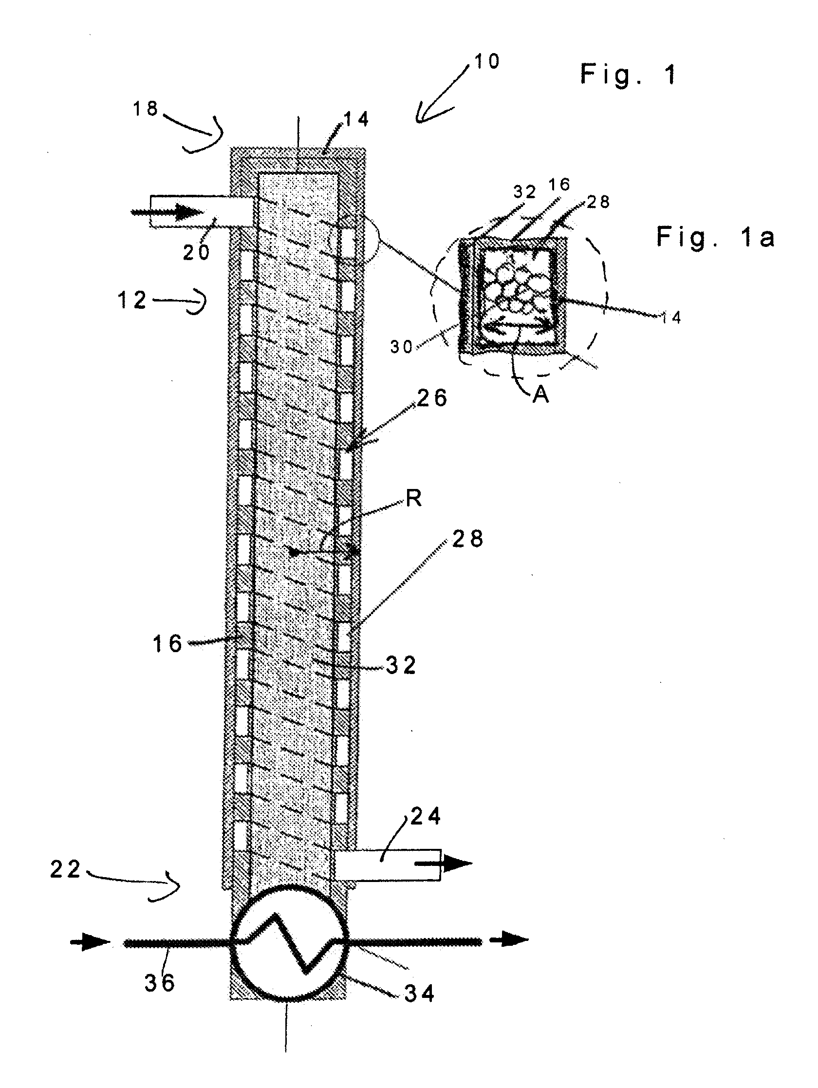
[0016]FIG. 1 shows a reformer 10 for a fuel cell system comprising a heat pipe 12 including an outer pipe wall 14 and an inner defining wall 16 both of which have a circular cylindrical shape. At a first axial end 18 of the heat pipe 12, there is provided a chamber inlet 20 through which a reactant gas mixture of, for example, air and evaporated fuel can enter the reformer. Disposed at a second axial end 22 of the heat pipe 12 is a chamber outlet 24 via which the reformed gas can exit the reformer 10. Outer pipe wall 14 and inner wall 16 define a chamber 26 extending between the chamber inlet 20 and chamber outlet 24. The chamber 26, in the embodiment as shown in this case, has a helical configuration between the chamber inlet 20 and chamber outlet 24. This is achieved by a passageway 28 being machined in the inner cylindrical wall 16. The dimension A of the passageway 28 in the radial direction of the heat pipe 12 is smaller than the radius R of the heat pipe 12. Arranged in the he...


PUM


Abstract

A reformer (10) for a fuel cell has a chamber (26) including a chamber inlet (20) for the input of a reactant gas mixture and a chamber outlet (24) for the output of a reformed gas, a catalytic active medium being arranged in the chamber. The reformer (10) has a heat pipe (12) with an outer cylindrical pipe wall (14) and an inner cylindrical wall (16), the chamber (26) being disposed between the outer pipe wall (14) and the inner wall (16). Advantageously, the heat pipe has a passage with a helical shapes.

Description

BACKGROUND OF THE INVENTION[0001]1. Field of the Invention[0002]The invention relates to a reformer for a fuel cell comprising a chamber including a chamber inlet for the input of a reactant gas mixture and a chamber outlet for the output of a reformed gas, a catalytic active medium being arranged in the chamber.[0003]2. Description of Related Art[0004]Generic reformers have numerous fields of application, they particularly serving to supply a fuel cell with a hydrogen-rich gas mixture from which electrical energy can be generated on the basis of electrochemical reactions. Such fuel cells are utilized, for example, as auxiliary power units (APUs) in motor vehicles.[0005]Reformer design is governed by a wealth of different factors. In addition to taking into account the properties of the reaction system, the economic embodiments are of importance, for example, particularly, also as regards integrating the reformer in its environment, the latter also involving how the inlet and outlet...

Claims


Application Information

Patent Timeline
IPC IPC(8): H01M8/18
CPCC01B3/386C01B2203/0261C01B2203/066C01B2203/0883Y02E60/50H01M8/04029H01M8/04059H01M8/0631H01M8/04014H01M8/04H01M8/06
Inventor MUEHLNER, MARCOLINDERMEIR, ANDREAS
Owner EHNERDEJ GMBKH
Why Eureka
Try Eureka