
Stabilization system and method for the fixation of bone fractures

a stabilization system and bone fracture technology, applied in the field of stabilization system and method for the fixation of fractures, can solve the problems of not being able to drill through such materials, materials cannot be easily cannot be easily manipulated and customized once installed on a patient, etc., to facilitate the stabilization and fixation of bone fractures

Inactive Publication Date: 2009-10-08
POGO SCREW
View PDF99 Cites 86 Cited by
  • Summary
  • Abstract
  • Description
  • Claims
  • Application Information

AI Technical Summary

Benefits of technology

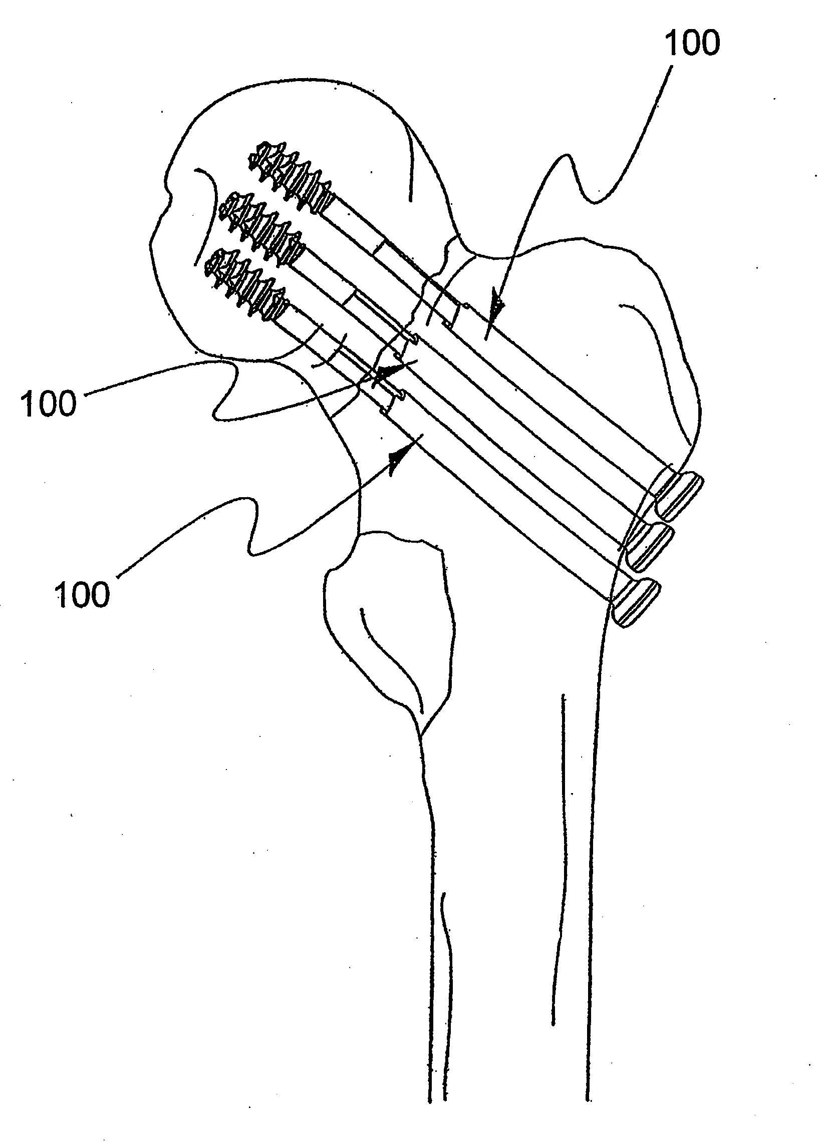
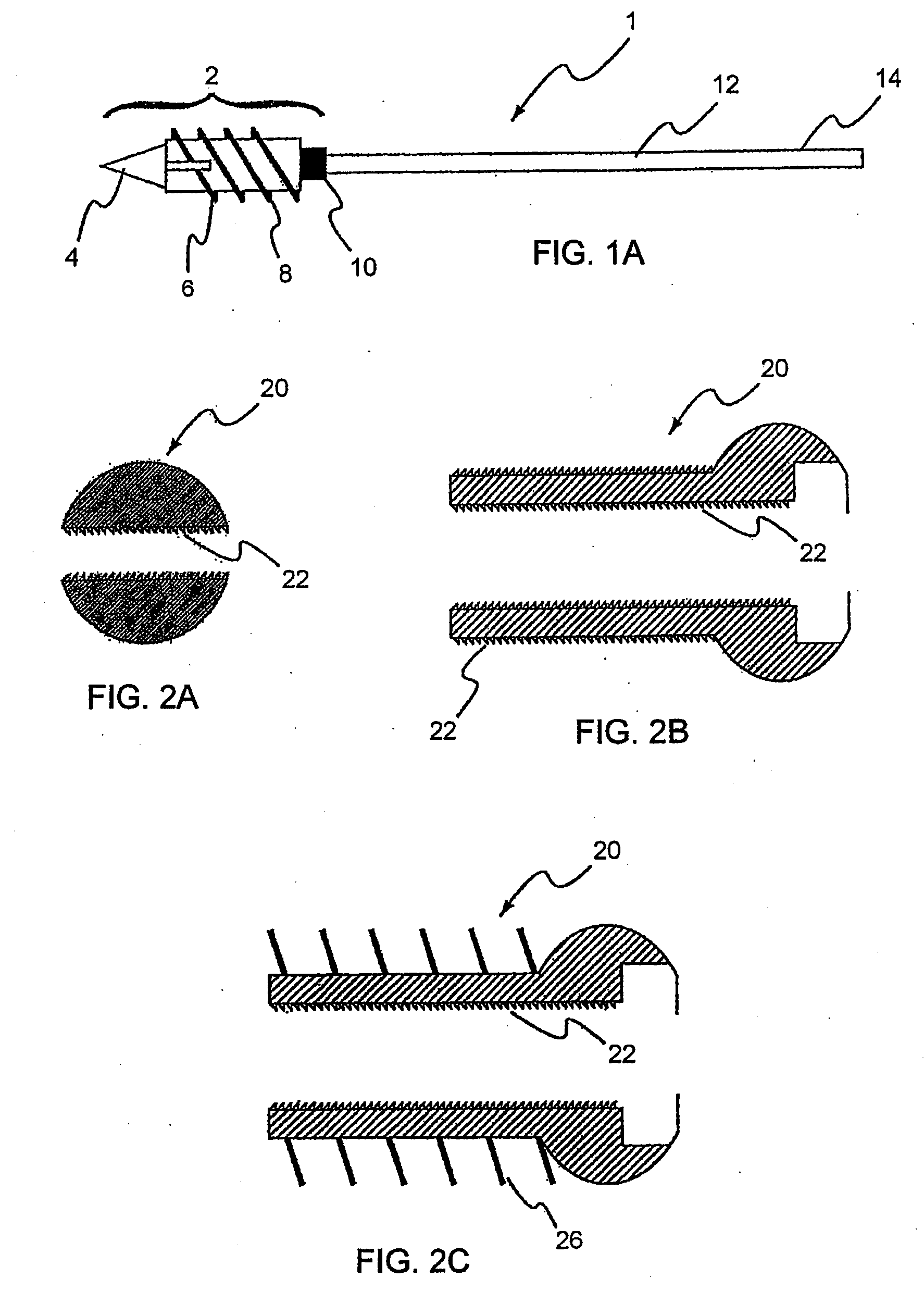
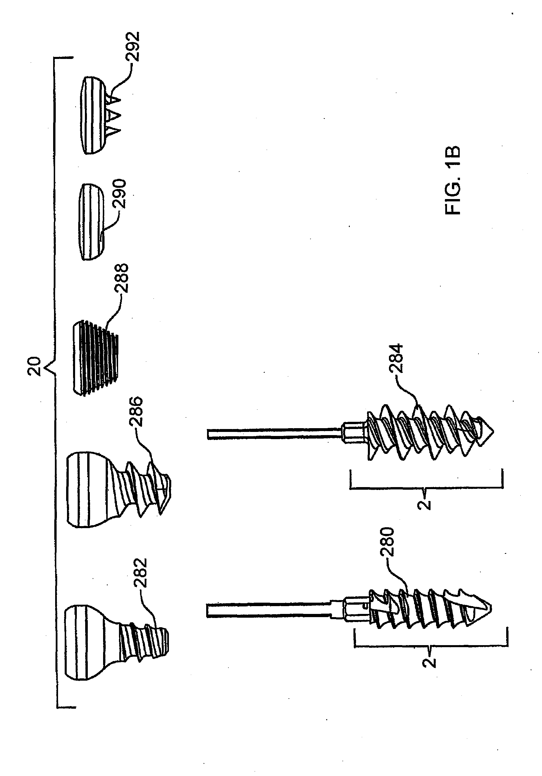
"The invention is a device that helps stabilize and fix bone fractures. It can be used without any pre-established holes for a fastener and can be sterilized and drilled to insert a fastener at a desired location. The device can be a bone plate, locking plate, intermedullary rod, or artificial vertebrae. The material used for the device can be plastic or other inert, moldable, or non-metallic material."

Problems solved by technology

However, one disadvantage of such conventional materials is that they cannot be easily manipulated and customized once installed on a patient.
For example, these materials cannot be easily molded to the unique shape of a patient's bone.
Another disadvantage of these conventional materials is that the physician may not be able to drill through such materials.
Additionally, if drilling is possible, drilling holes in these materials after the stabilization device has been placed in a patient, or during preparation within an operating room, creates metal shavings that can be harmful to a patient's health.
Such “one-size-fits-all” pre-located openings may not be oriented in an optimal position and / or angle for securing the device to the unique shape of a patient's bone.
Moreover, unnecessary openings in the stabilization device can degrade the strength and integrity of the device, thereby decreasing efficacy.

Method used


Image

  • Stabilization system and method for the fixation of bone fractures
  • Stabilization system and method for the fixation of bone fractures
  • Stabilization system and method for the fixation of bone fractures

Examples


Embodiment Construction

[0049]The present invention is described herein and includes various exemplary embodiments in sufficient detail to enable those skilled in the art to practice the invention, and it should be understood that other embodiments may be realized without departing from the spirit and scope of the invention. Thus, the following detailed description is presented for purposes of illustration only, and not of limitation, and the scope of the invention is defined solely by the appended claims. The particular implementations shown and described herein are illustrative of the invention and its best mode and are not intended to otherwise limit the scope of the present invention in any way.

[0050]In general, the present invention facilitates the change in distance between objects, object portions, or surfaces, compresses objects or object portions together, and / or provides a configurable or random amount of pressure between surfaces. The system may facilitate changing, maintaining, reducing and / or ...


PUM


Abstract

A bone stabilization device which permits a user to drill one or more holes at a desired location and trajectory for insertion of a fastener. The stabilization device may comprise a bone plate, a locking plate, an intermedullary rod, and / or an artificial vertebrae. The stabilization device may comprise a portion of penetrable material, such as polyetheretherketone or other inert material.

Description

CROSS-REFERENCE TO RELATED APPLICATIONS[0001]This application is a continuation-in-part of, and claims priority to, U.S. Ser. No. 12 / 258,013 filed Oct. 24, 2008 and entitled “BONE SCREW SYSTEM AND METHOD,” which itself is a continuation-in-part of U.S. Ser. No. 12 / 104,658 filed Apr. 17, 2008 and entitled “ADJUSTABLE BONE PLATE FIXATION SYSTEM AND METHOD, which itself is a continuation-in-part of U.S. Ser. No. 11 / 952,715, filed on Dec. 7, 2007 and entitled “BONE SCREW SYSTEM AND METHOD”, which is itself a continuation-in-part of U.S. Ser. No. 11 / 742,457, filed on Apr. 30, 2007 and entitled CANNULATED BONE SCREW SYSTEM AND METHOD which itself is a continuation-in-part of, and claims priority to, U.S. Ser. No. 11 / 678,473, filed on Feb. 23, 2007 and entitled SYSTEM AND METHOD FOR A CAP USED IN THE FIXATION OF BONE FRACTURES which itself is a continuation-in-part of, and claims priority to, U.S. Ser. No. 10 / 779,892, filed on Feb. 17, 2004 and entitled SYSTEM AND METHOD FOR THE FIXATION O...

Claims


Application Information

Patent Timeline
Patent Type & Authority Applications(United States)
IPC IPC(8): A61B17/56
CPCA61B17/742A61B17/744A61B17/746A61B17/8004A61B17/8047A61B17/8877A61B17/861A61B17/8625A61B17/8685A61B17/8863A61B17/8869A61B17/8057
Inventor TIPIRNENI, KISHOREVASSELLO, WAYNE
Owner POGO SCREW
Learn More