Methods, systems, and kits for plaque stabilization

a plaque stabilization and plaque technology, applied in the field of medical devices and methods, can solve the problems of unstable plaque, patient may be and plaque is at risk of converting to unstable plaque, etc., and achieve the effect of non-uniform peripheral energy distribution over the circumference of the arterial wall and the patient's asymptomatic but at significant risk of cardiovascular diseas

Inactive Publication Date: 2002-03-14
PHARMASONICS
View PDF0 Cites 97 Cited by
  • Summary
  • Abstract
  • Description
  • Claims
  • Application Information

AI Technical Summary

Benefits of technology

[0015] Treatment according to the present invention is effected by exposing a target region within a blood vessel of the patient to vibrational energy at a mechanical index and for a time sufficient to promote endothelial restoration within the target region. It has been found that the strength of the vibrational energy (as measured by the mechanical index) and the duration of the treatment (as measured by elapsed treatment time, duty cycle, and pulse repetition frequency (PRF)) can be selected to increase the thickness and strength of the thin fibrotic cap which covers the lipid pool which is characteristic of unstable intravascular plaque. It is believed that the vibrational energy may act to increase fibroblast proliferation and collagen and non-collagenous protein synthesis, which in turn increases the thickness of the fibrotic cap. Additionally, it is believed that the vibrational energy may also promote the maturation of the lipid pool within the plaque, further promoting plaque stability and decreasing the risk of plaque rupture.
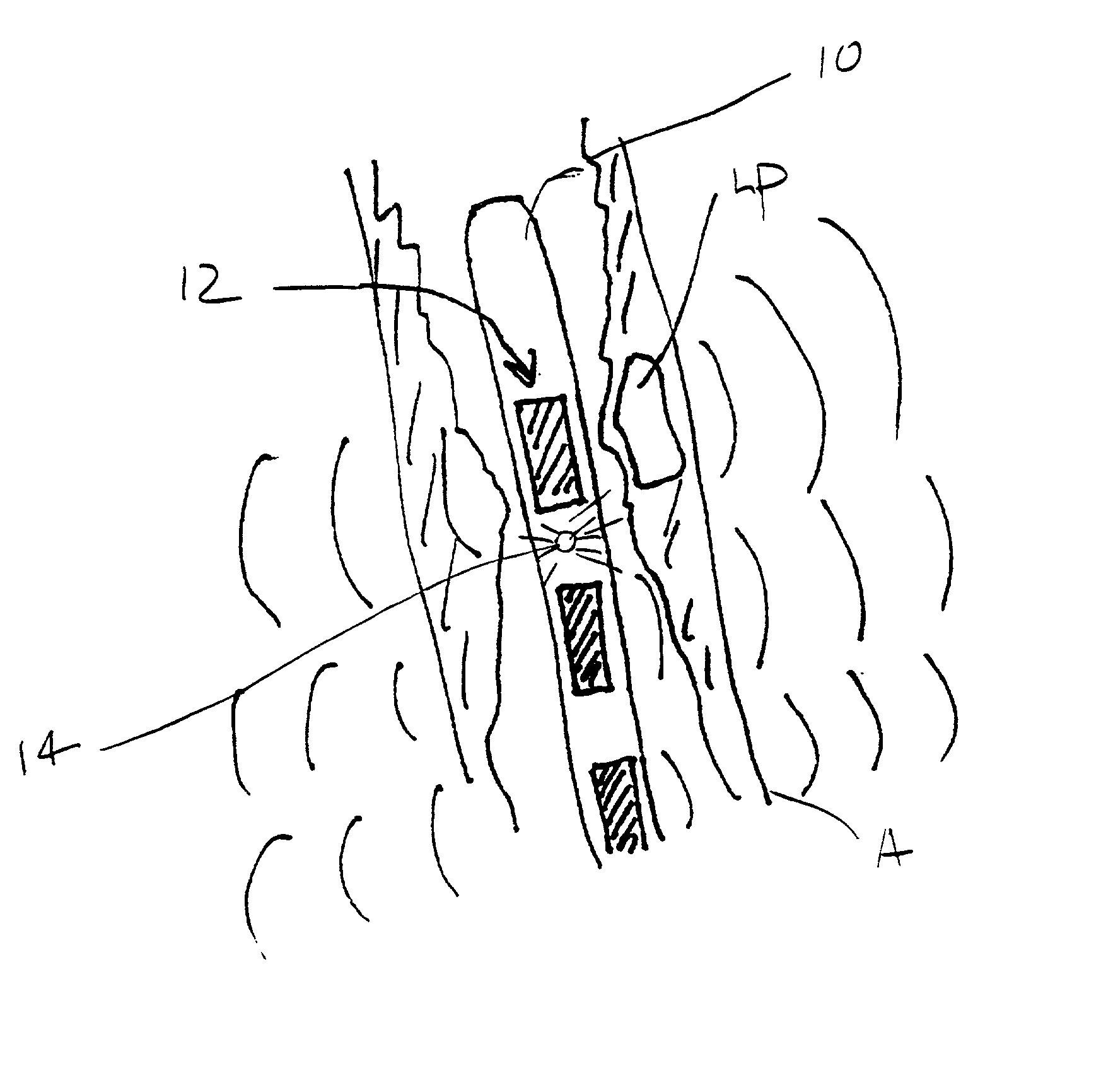
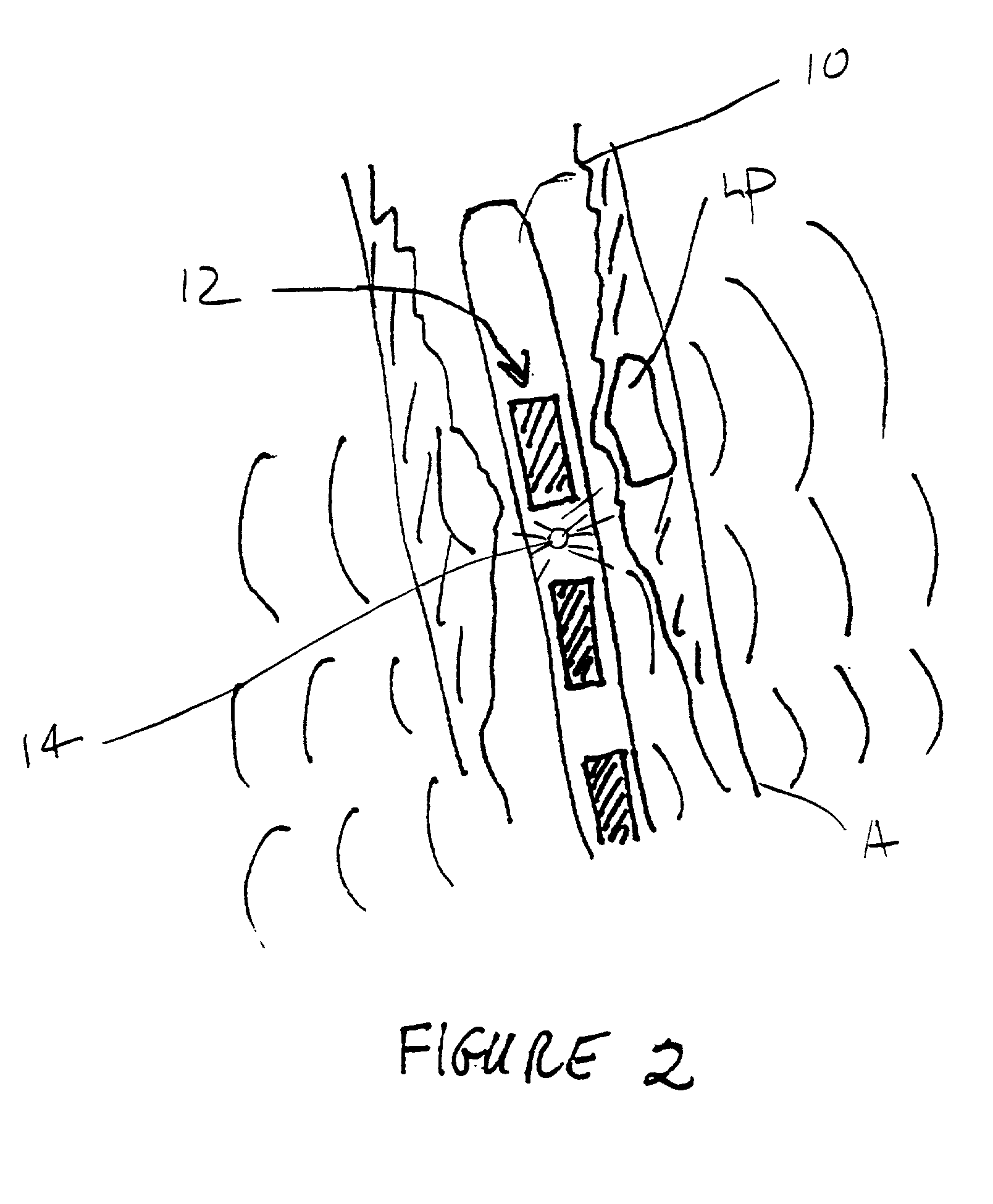
[0019] Once it is determined that therapy according to the present invention is to be performed, the particular motive therapy can be selected among different approaches. In a first approach, exposing the blood vessel to vibrational energy comprises positioning an interface surface on or coupled to a vibrational transducer within the blood vessel at a target site within the target region. The transducer is driven to direct vibrational energy from the interface surface against the blood vessel wall to enhance growth and stabilization of the fibrotic cap over the lipid-rich unstable plaque. Alternatively, the exposing step may comprise positioning an interface surface on or coupled to a vibrational transducer against a tissue surface which is disposed over the target region of the blood vessel, e.g., over the epicardium or pericardium of the heart, or over a skin surface, such as the leg, when treating the peripheral vasculature. The transducer may be then driven to direct vibrational energy from the interface surface through overlying tissue and against the blood vessel wall. When employing such external techniques, the vibrational energy may be directed toward a beacon or other signal located within the target region. As a third alternative, an interface surface on or coupled to a vibrational transducer may be positioned within a second blood vessel located near the target region of the target blood vessel. For example, coronary and other veins are frequently located a short distance from a corresponding artery. By placing the interface surface within a vein, a vibrational energy can be directed to an adjacent artery for treatment of disease within that artery. As with the prior cases, the transducer will then be driven to direct vibrational energy from the interface surface, in this case present within the second blood vessel, through tissue between the second blood vessel and the target blood vessel, and into the blood vessel wall of the target blood vessel. As a still further alternative, an interface surface coupled on or to a vibrational transducer may be positioned within a heart chamber to treat a coronary artery positioned over the heart chamber. The transducer will be driven to direct vibrational energy outwardly from the heart chamber through the myocardium and into the coronary artery in order to treat the coronary wall. As a fifth alternative, tissue overlying a target blood vessel may be surgically opened to directly expose the blood vessel. An interface surface on or coupled to a vibrational transducer may then be directly engaged against the wall of the target blood vessel (or over some thin layer of tissue or other structures which may remain), and the transducer driven to direct vibrational energy into the target region of the exposed target vessel.
[0021] The duration of treatment is defined as the actual time during which vibrational energy is being applied to the arterial wall. Duration will thus be a function of the total elapsed treatment time, i.e., the difference in seconds between the initiation and termination of treatment; burst length, i.e., the length of time for a single burst of vibrational energy; and pulse repetition frequency (PRF). Usually, the vibrational energy will be applied in short bursts of high intensity (power) interspersed in relatively long periods of no excitation or energy output. An advantage of the spacing of short energy bursts is that heat may be dissipated and operating temperature reduced.
[0026] Even when vibratory forces are spaced-apart peripherally and / or longitudinally, the effective distribution of vibrational energy will be evened out by radiation pressure forces arising from the absorption and reflection of ultrasound on the circumferential walls of the arterial lumen, thereby producing a uniform effect due to the fact that the tension in the wall of the lumen will tend to be equal around its circumference. Accordingly, a uniform inhibitory effect can occur even if there is some variation in the intensity of the ultrasound (as in the case of the non-isotropic devices described hereinafter). This is due to the fact that the tension around the circumference of the lumen will be equal in the absence of tangential forces.

Problems solved by technology

Often, the patient will have a symptom which will trigger the evaluation, such as angina, chest pain, or the like.
In other cases, however, the patient may be asymptomatic but at significant risk of cardiovascular disease.
Even when the plaque is believed to be stable, treatment may be warranted if the plaque load is particularly heavy or it is believed that the plaque is at risk of converting to unstable plaque in the future.
In particular, it is believed that a non-uniform peripheral distribution of energy over the circumference of the arterial wall will find use, at least so long as at least most portion of walls are being treated.

Method used


Image

  • Methods, systems, and kits for plaque stabilization
  • Methods, systems, and kits for plaque stabilization
  • Methods, systems, and kits for plaque stabilization

Examples


Embodiment Construction

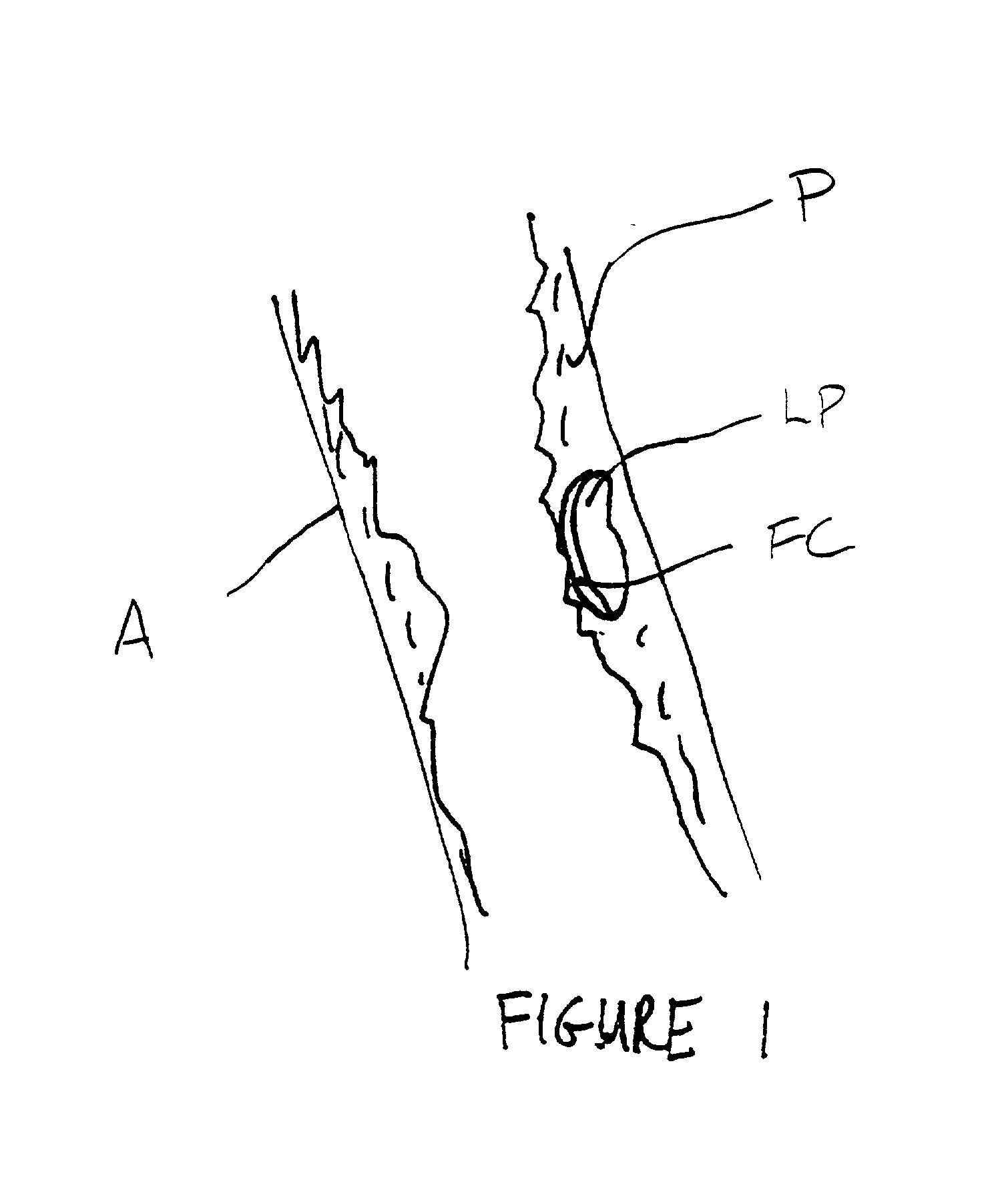
[0039] FIG. 1 illustrates a longitudinal cross-section of a blood vessel, in this case an artery A having a region of plaque including heterogeneous plaque P within an unstable region comprising a lipid pool LP covered by a fibrotic cap FC. The nature of the plaque P and location of the unstable regions within the plaque may be determined by the techniques described above.

[0040] Once it is determined that the patient suffers from unstable plaque, or it is determined that the patient has apparently stable plaque which might benefit from stability enhancement, the patient may be treated by exposing the plaque, and in particular unstable regions of the plaque, to vibrational energy with the treatment parameters described above. Usually, the entire region of plaque which has been identified will be treated, although as diagnostic capabilities become more advanced, it may be desirable to treat only the regions of instability within the plaque.

[0041] For example, referring to FIG. 2, an i...


PUM


Abstract

Atherosclerotic plaque and blood vessels may be stabilized by directing vibrational energy, typically ultrasonic energy, into the adjacent blood vessel wall. Application of the vibrational energy, optionally in combination with growth factors, growth factor genes, or other substances which enhance growth instability of a fibrotic cap over the plaque, will reduce the risk of rupture of unstable plaque and inhibit the conversion of stable plaque into unstable plaque.

Description

CROSS-REFERENCES TO RELATED APPLICATIONS[0001] This application claims the benefit of prior provisional application No. 60 / 187,778 filed on Mar. 9, 2000, under 37 CFR 1.78(a)(3), the full disclosure of which is incorporated herein by reference.[0002] 1. Field of the Invention[0003] The present invention relates generally to medical devices and methods. More particularly, the present invention relates to devices and methods for the treatment and stabilization of intravascular plaque.[0004] Coronary artery disease resulting from the build-up of atherosclerotic plaque in the coronary arteries is a leading cause of death in the United States and worldwide. The plaque build-up causes a narrowing of the artery, commonly referred to as a lesion, which reduces blood flow to the myocardium (heart muscle tissue). Myocardial infarction (better known as a heart attack) can occur when an arterial lesion abruptly closes the vessel, causing complete cessation of blood flow to portions of the myoca...

Claims


Application Information

Patent Timeline
Patent Type & Authority Applications(United States)
IPC IPC(8): A61B17/00A61B17/22A61B18/00A61N7/00
CPCA61B17/2202A61B2017/00243A61B2017/22001A61B2017/22054A61B2017/22062A61N7/00A61N2007/0078
Inventor BRISKEN, AXELMOORE, PAULINAZUK, ROBERT
Owner PHARMASONICS
Why Eureka
Try Eureka