Flexible spinal stabilization

a spinal stabilization and flexible technology, applied in the field of flexible spinal stabilization, can solve the problems of small bone fissures and cracks near the bone anchor interface, failure of the anchor system, and decreased performance, so as to reduce the probability of the anchor being rocked loose of the vertebrae in which it is seated, and absorb the effect of for

Inactive Publication Date: 2008-04-24
VESSA PAUL PETER
View PDF12 Cites 99 Cited by
  • Summary
  • Abstract
  • Description
  • Claims
  • Application Information

AI Technical Summary

Benefits of technology

[0006]Embodiments of the present invention may be used to link or otherwise connect vertebrae of the spine. These connections may be made with screws or other anchors fixedly connected to the vertebrae and a bridge linking the embedded anchors together. In embodiments of the invention, the bridge and / or the anchors may be configured to mimic the natural connections of vertebrae of the spine. This may include sizing the dimensions of the bridge such that it opposes the physical forces placed on it much in the same manner as the natural connections the bridge is replacing or supplementing. In some instances, the bridge and anchors may be configured to reduce or absorb the amount of force exerted on the anchors. When these forces are reduced, the likelihood that the anchor will be rocked loose of the vertebrae in which it is seated may be reduced.

Problems solved by technology

This decay can result as small bone fissures and cracks are created near the bone anchor interface due to the rocking motion or opposing forces.
Overtime this can cause decreased performance and even failure of an anchor system.

Method used


Image

  • Flexible spinal stabilization
  • Flexible spinal stabilization
  • Flexible spinal stabilization

Examples


Embodiment Construction

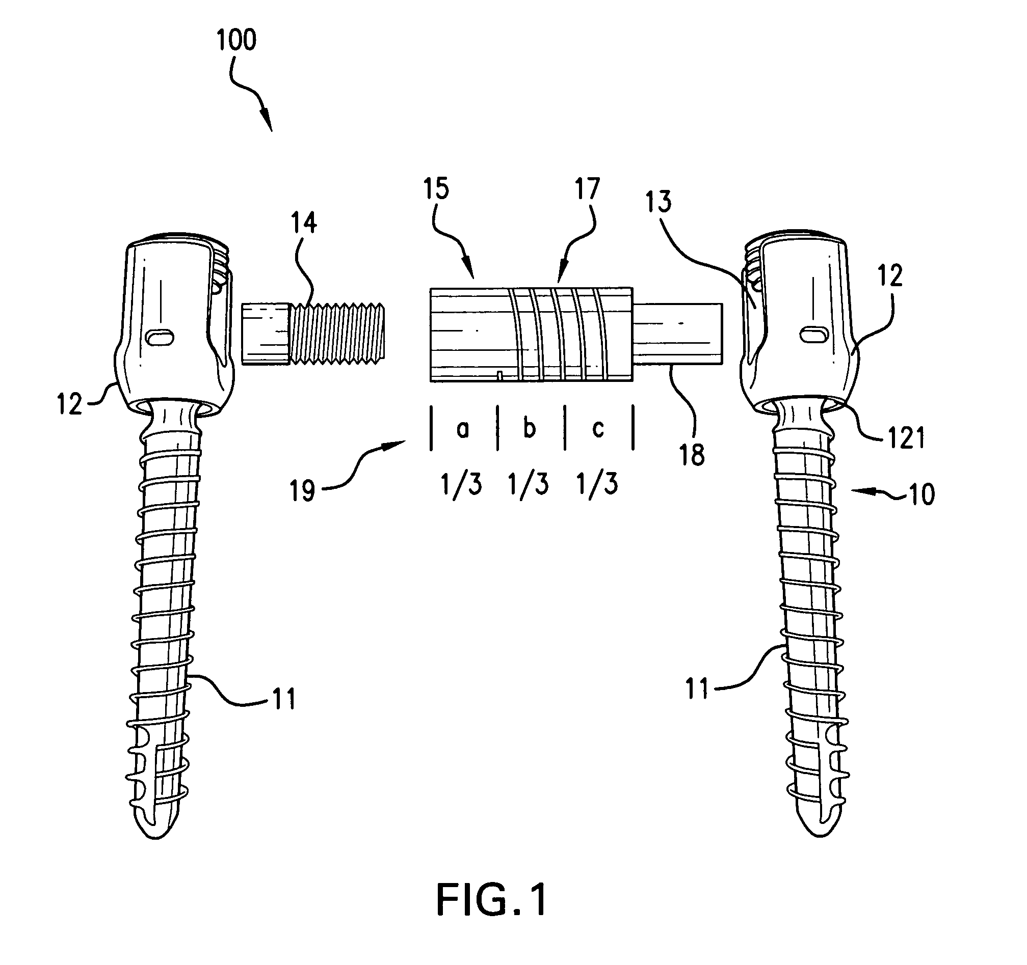
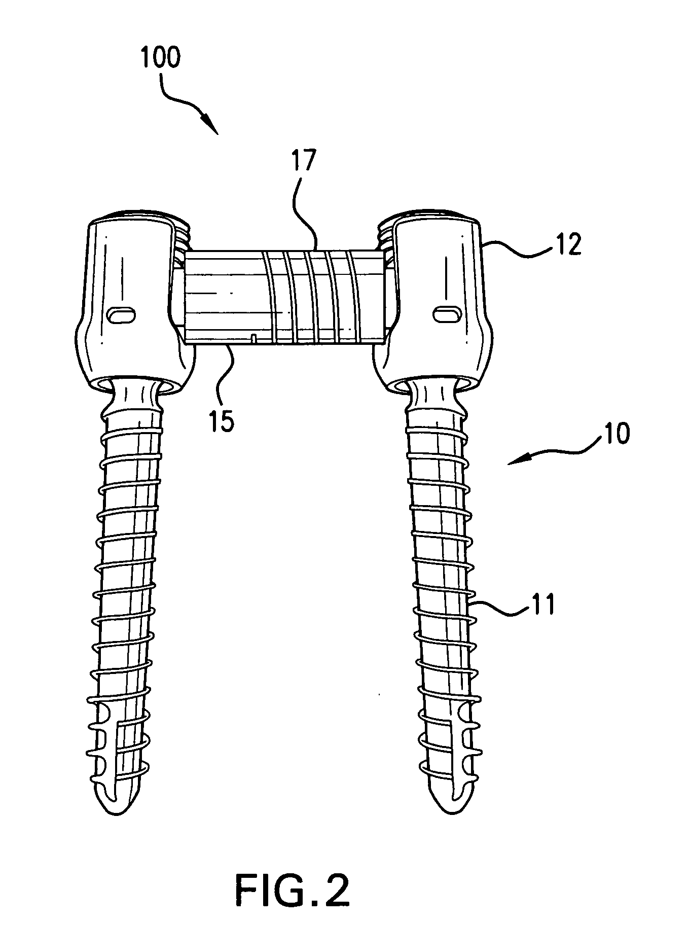
[0026]FIG. 1, which is an exploded view of a spinal support system as may be employed in accord with the current invention, shows two pedicle screws 10, each pedicle screw having a screw head 12 and screw threads 11. The screw head 12 is shown coupled to the screw threads 11 through a ball joint 121. FIG. 1 also shows an insert 14 and a bridging spring 16. As can be seen, the bridging spring 16 contains three portions: a solid section 15, a coiled section 17, and an insert section 18. Also shown in FIG. 1 are spring distance markers. As can be seen from these markers, approximately one-third of a larger diameter section of the spring 16 is a non-coiled or solid portion 15, while two-thirds of this larger diameter section of the spring 16 is a coiled section 17. As can also be seen in FIG. 1, the insert section 18 is roughly one-third of the overall length of the spring 16 and is also roughly equal to the combined length of the solid section 15 and the spring section 16. Insert 14 ma...


PUM


Abstract

The invention regards spinal stabilization. It may include a spinal support system having spinal anchors and a bridge coupled to the anchors wherein the bridge has a length with a more flexible section and a less-flexible section. The less flexible section may be at an end of the bridge and the more flexible section may be off centered between the two spinal anchors. It may also include a kit having some or all of these components as well as spacers. It may further include a method of designing a spinal stabilization system this method may include identifying three-dimensional loads placed at a location of a spinal column, identifying three-dimensional ranges of motion for that location of the spinal column, quantifying the forces associated with the identified loads, and designing a spring bridge to transfer some but not all of the loads for at least one of the axes from one end of the spring bridge to another end of the spring bridge, the load not transferred being absorbed at least partially by flexure of the spring bridge.

Description

FIELD OF THE INVENTION [0001]The present invention regards providing flexible supports for a spinal column. More specifically, the present invention regards a flexible connection system for linking vertebrae of a spinal column, kits containing these flexible systems, and methods for designing and installing these flexible systems.BACKGROUND OF THE INVENTION [0002]The human spinal column consists of a series of thirty-three stacked vertebrae. Each vertebrae is separated by a disc and includes a vertebral body having several posterior facing structures. These posterior structures include pedicles, lamina, articular processes, and spinous process. The articular processes, which function as pivoting points between vertebrae, include left and right superior and inferior processes. The superior and inferior processes of adjacent vertebrae mate with each other to form joints called facet joints. In a typical pair of vertebrae, the inferior articular facet of an upper vertebrae mates with t...

Claims


Application Information

Patent Timeline
Patent Type & Authority Applications(United States)
IPC IPC(8): A61B17/58A61B17/56
CPCA61B17/7014A61B17/7032A61B17/7028
Inventor VESSA, PAUL PETER
Owner VESSA PAUL PETER
Why Eureka
Try Eureka