
Method and user interface for implementation of a medical examination

a user interface and medical examination technology, applied in the field of medical examination implementation methods and user interfaces, can solve the problems of many setting possibilities, complex and detailed dependencies among individual parameters, and the effect of reducing cognitive effor

Inactive Publication Date: 2009-10-08
SIEMENS HEALTHCARE GMBH
View PDF11 Cites 8 Cited by
  • Summary
  • Abstract
  • Description
  • Claims
  • Application Information

AI Technical Summary

Benefits of technology

[0019]It is an advantage of the invention that the workflows in the image acquisition can be optimized to a significant degree for the following reasons. The parameters are more easily found because they are identifiable not only via the column names but additionally via the (relative) position in the two-dimensional area. The cognitive effort is reduced because the user interface is more clear (input fields are only displayed upon focusing) and demand less memory capacity of the operator. The navigation is simpler (sub-cards are omitted, redundancies are remedied, the user interaction is inherently faster and requires less effort). Automatic parameter adaptations (Conflict Solver) no longer interrupt the workflow; its results are clearly shown; alterations can be made quickly, be clearly visualized and be canceled.
that the workflows in the image acquisition can be optimized to a significant degree for the following reasons. The parameters are more easily found because they are identifiable not only via the column names but additionally via the (relative) position in the two-dimensional area. The cognitive effort is reduced because the user interface is more clear (input fields are only displayed upon focusing) and demand less memory capacity of the operator. The navigation is simpler (sub-cards are omitted, redundancies are remedied, the user interaction is inherently faster and requires less effort). Automatic parameter adaptations (Conflict Solver) no longer interrupt the workflow; its results are clearly shown; alterations can be made quickly, be clearly visualized and be canceled.

Problems solved by technology

This turns out to be extremely involved and complicated since, depending on the imaging method, there can be up to 200 parameters.
Moreover, very complex and detailed dependencies exist among the individual parameters.
These many setting possibilities are complicated and, among other things, confuse the operator.

Method used


Image

  • Method and user interface for implementation of a medical examination
  • Method and user interface for implementation of a medical examination
  • Method and user interface for implementation of a medical examination

Examples


Embodiment Construction

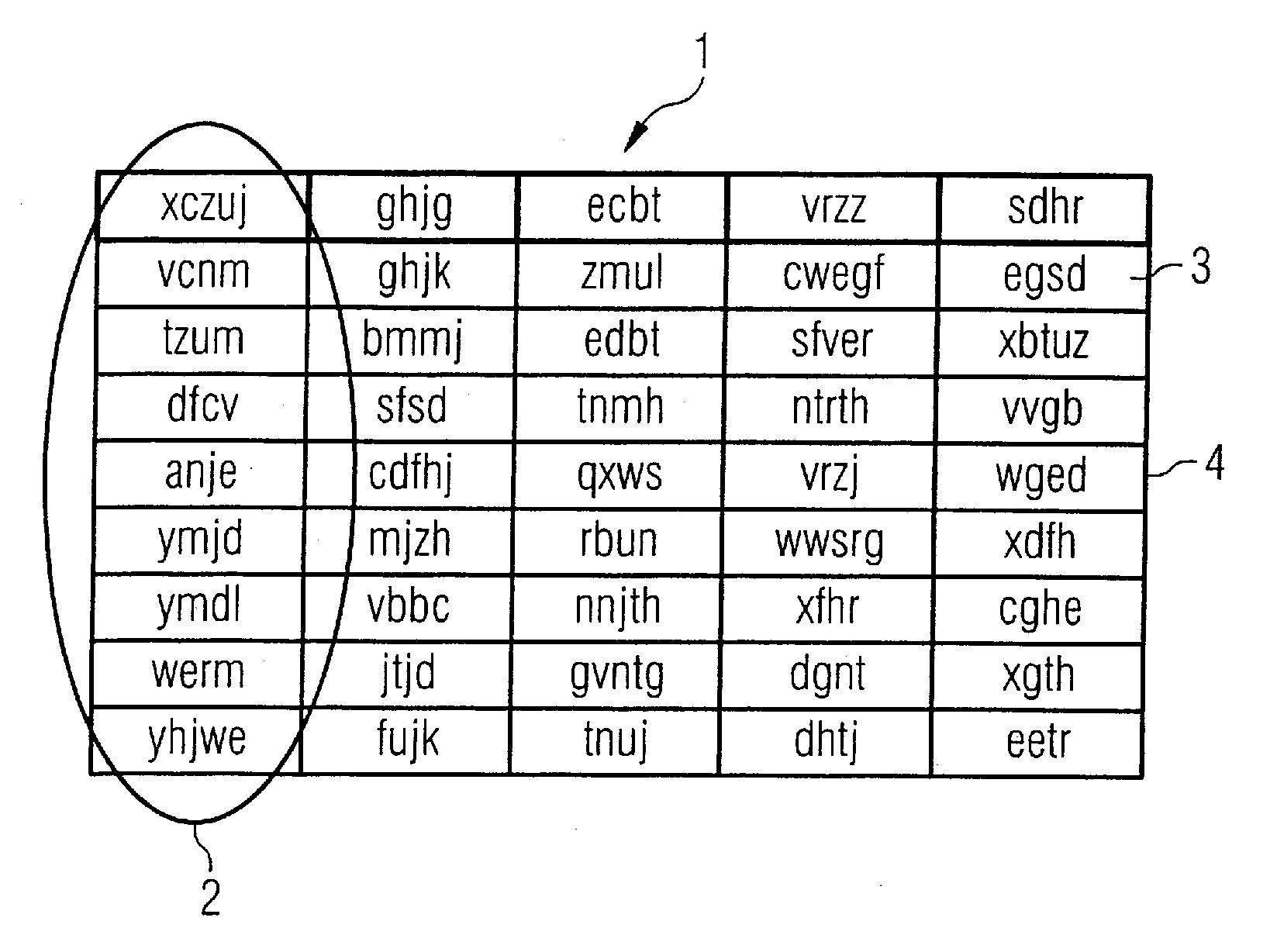
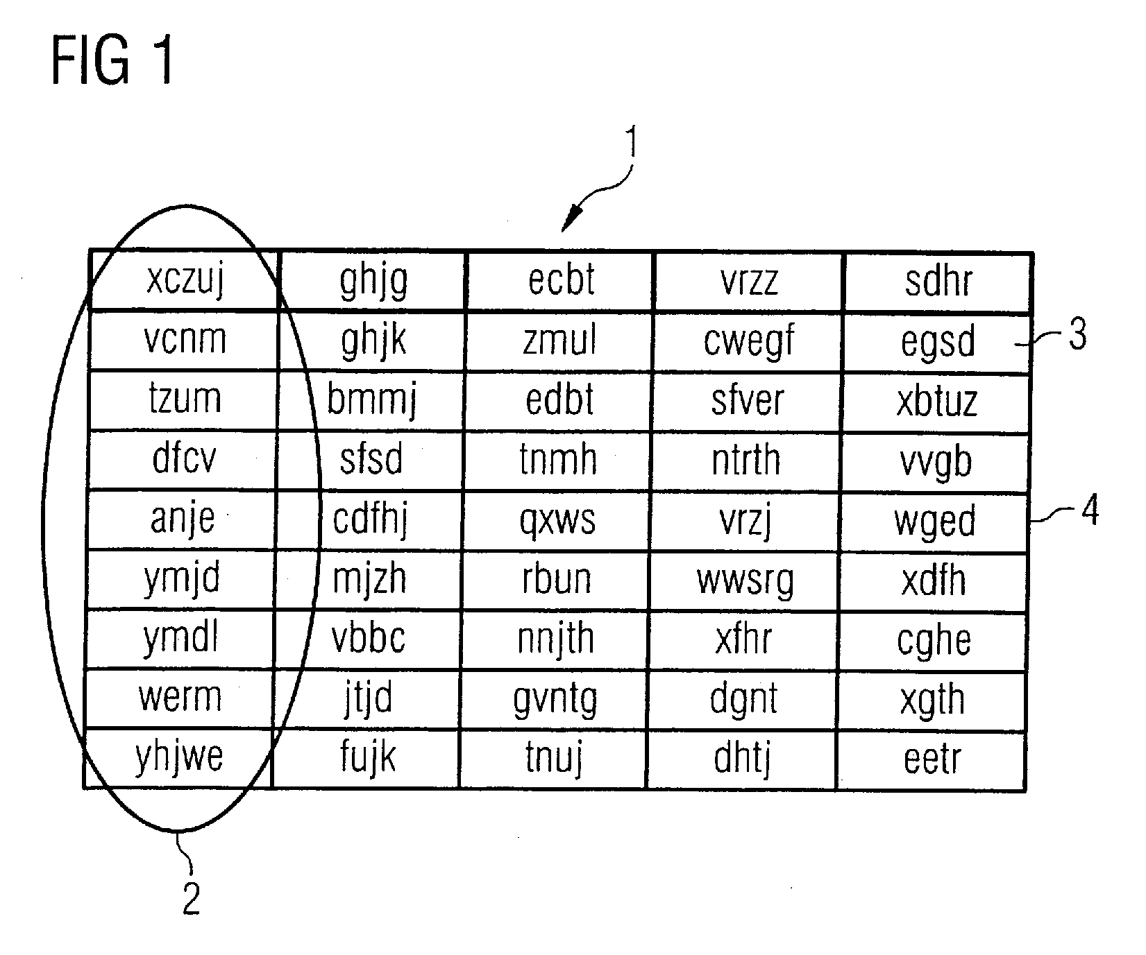
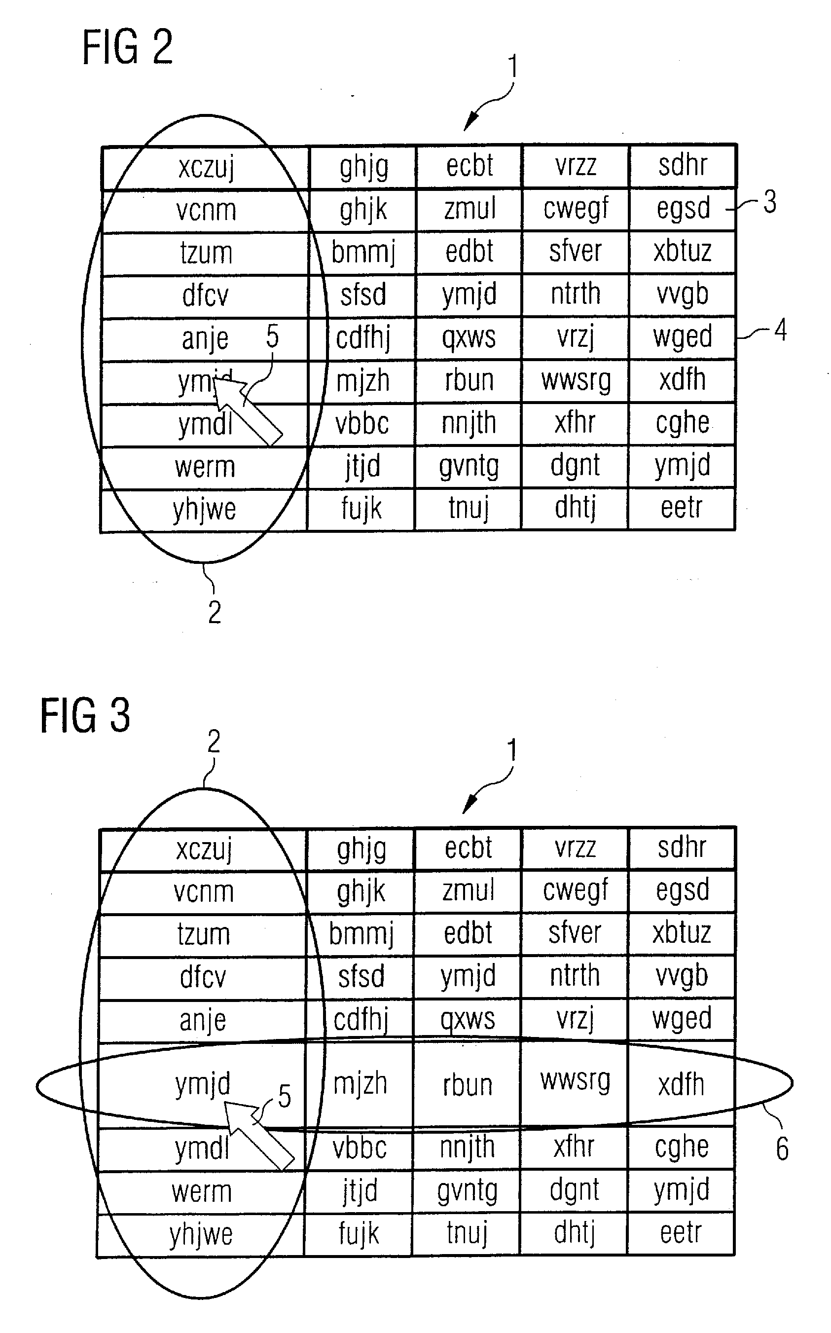
[0022]A matrix 1 as it is displayed on a screen of a user interface is shown in FIG. 1. Those measurement parameters that belong to a common theme are collected in columns 2 in the matrix 1. For example, these can be parameters that specify a “routine” in the image acquisition (for example with a magnetic resonance apparatus) for a medical examination. These parameters are “Slice group”, “Slices”, “Distance” etc. A different group of measurement parameters can be collected under the heading “Geometry”, and this group contains the parameters “Multislice mode”, “Series”, “Links”, for example. Additional groups are “Contrast”, “System” and “Physio”. The group designations are shown in bold face as column headings in this embodiment.

[0023]In the shown embodiment, initially only designations 3 of the measurement parameters in individual measurement parameter cells 4 are indicated in the matrix itself, thus the cited terms “Slice group”, “Slices”, “Distance”. Instead of concrete terms, he...


PUM


Abstract

In a method for the implementation of a medical examination via the user interface of at least one imaging device, parameter values in a group of measurement parameters are determined, and are entered via an input device of the user interface. Spatially resolved image information are generated by the at least one imaging device depending on the group of measurement parameters, and the image information is stored on a storage medium. The image information are presented as a data symbol on a screen of the user interface. In order to present the parameters and dependencies to enable a more efficient work process, each measurement parameter of the group of measurement parameters is respectively presented on the screen in a measurement parameter cell of a matrix with multiple rows and multiple columns. The measurement parameters can be contained at least in part in multiple measurement parameter cells. The presentation size of the multiple columns of the matrix depends on their distance from the pointer symbol on the screen.

Description

BACKGROUND OF THE INVENTION[0001]1. Field of the Invention[0002]The present invention concerns the setting of measurement parameters for the implementation of medical examinations with imaging methods. In particular, the invention concerns a method and a user interface for implementation of a medical examination.[0003]2. Description of the Prior Art[0004]In software for the implementation of imaging methods in medical technology (for example magnetic resonance tomography, computed tomography, etc.) it regularly occurs that the operator must adapt individual parameters of one or more scan protocols in the data acquisition (known as the “scan”). An access to all possible parameters is sometimes necessary. This turns out to be extremely involved and complicated since, depending on the imaging method, there can be up to 200 parameters. Moreover, very complex and detailed dependencies exist among the individual parameters.[0005]In parameter groups of the type known as the “exam card” of ...

Claims


Application Information

Patent Timeline
Patent Type & Authority Applications(United States)
IPC IPC(8): G05B11/01G06F3/048G06F3/0482G06F3/0484G16H30/40
CPCG06F3/0482G06F2203/04805G06F19/321G06F3/04847G16H30/40
Inventor GLASER-SEIDNITZER, KARLHEINZKLING, JOHANNESREQUARDT, MARTIN
Owner SIEMENS HEALTHCARE GMBH
Learn More