Multi-Piece Packing Element Containment System

a technology of containment system and packing element, applied in the direction of sealing/packing, fluid removal, borehole/well accessories, etc., can solve problems such as sealing failure, and achieve the effect of preventing or minimizing extrusion

Inactive Publication Date: 2009-10-15
BAKER HUGHES INC
View PDF12 Cites 76 Cited by
  • Summary
  • Abstract
  • Description
  • Claims
  • Application Information

AI Technical Summary

Benefits of technology

[0006]The invention provides methods and devices for containing a packer element in a set condition within a wellbore and for preventing or minimizing extrusion of the packer element after setting. An exemplary packer device is described which includes a plurality of deformable packer elements which radially surround a packer mandrel. One or more of the packer elements is contained against axial extrusion using a packer containment system. In a preferred embodiment, the packer containment system includes a flexible metal backup ring, which partially encases the packer element by substantially covering at least one axial side and a portion of the exterior radial surface of the packer element. The packer co

Problems solved by technology

One problem with packer devices of this type is that of extrusion of the packer element axially along the space betwe

Method used


Image

  • Multi-Piece Packing Element Containment System
  • Multi-Piece Packing Element Containment System
  • Multi-Piece Packing Element Containment System

Examples


Embodiment Construction

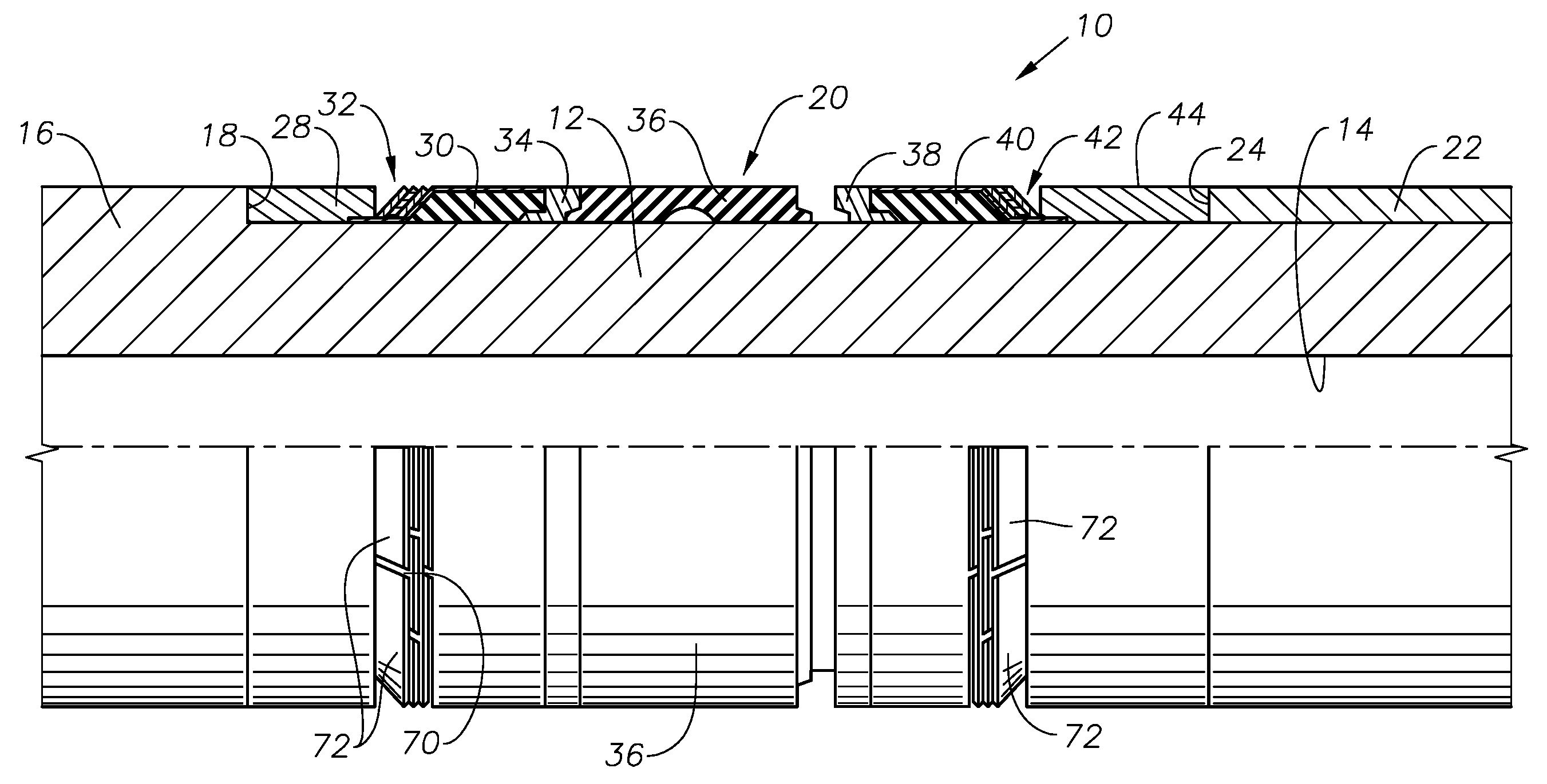
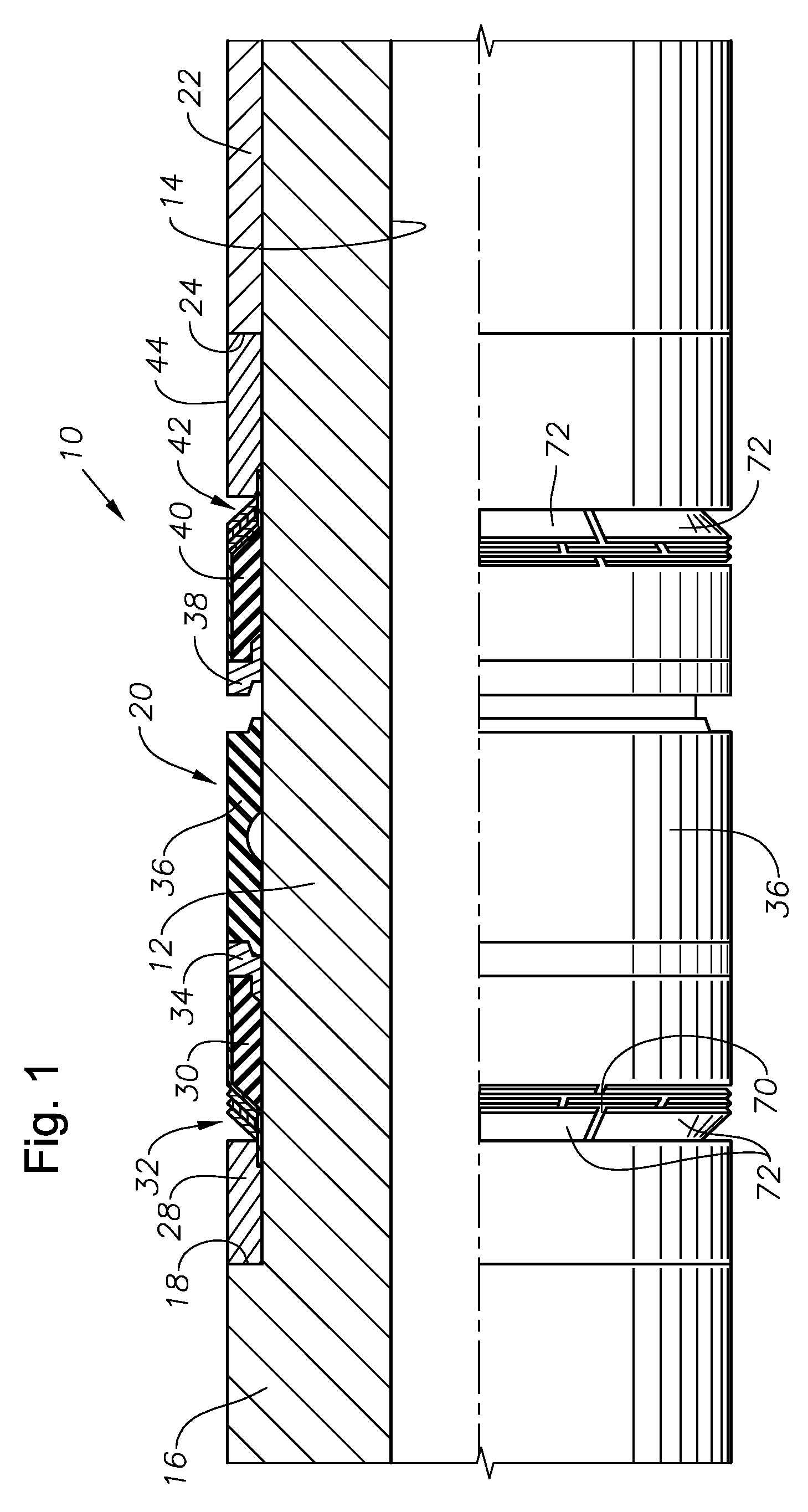
[0015]FIG. 1 illustrates an exemplary packer assembly 10 which includes a central packer mandrel 12. The packer mandrel 12 can be incorporated into a production tubing string or other work string (not shown), in a manner known in the art. A flowbore 14 is defined within the mandrel 12. The outer radial surface of the mandrel 12 has an expanded diameter portion 16 which presents a stop shoulder 18. Radially surrounding the packer mandrel 12 and immediately below the stop shoulder 18 is a packer element portion, generally indicated at 20, the structure of which will be described in greater detail shortly. A setting sleeve 22 radially surrounds the packer mandrel 12 below the packer element portion 20. The setting sleeve 22 is axially moveable with respect to the mandrel 12 and presents a compression end 24.

[0016]The exemplary packer element portion 20 depicted in FIG. 1 includes an upper end cone 28 which surrounds the mandrel 12 and abuts the stop shoulder 18. The packer element port...


PUM


Abstract

Methods and devices for retaining a packer element in a set condition within a wellbore and for preventing or minimizing extrusion of the packer element after setting. A packer device includes a plurality of deformable packer elements which radially surround a packer mandrel. One or more of the packer elements is contained against axial extrusion using a packer containment system. The packer containment system includes a flexible metal backup ring, which partially encases the packer element by substantially covering at least one axial side and a portion of the exterior radial surface of the packer element. The packer containment system also includes a plurality of annular support rings, or “petal rings” which have petal-shaped radial protuberances with slots between them.

Description

BACKGROUND OF THE INVENTION[0001]1. Field of the Invention[0002]The invention relates generally to packer devices used within a wellbore.[0003]2. Description of the Related Art[0004]Packers are used to create a fluid seal within a wellbore between a central work string, such as a production tubing string, and a surrounding tubular, such as a wellbore wall. A common packer design has a central mandrel with an elastomeric packer element surrounding the mandrel. The packer element is set by axially compressing it on the mandrel. As the packer element is compressed axially, the packer element is expanded radially outwardly and into contact with the surrounding surface.[0005]One problem with packer devices of this type is that of extrusion of the packer element axially along the space between the packer mandrel and the surrounding wellbore. This can occur as a result of high wellbore temperatures, pressures and / or caustic chemicals which act upon the packer element. Severe extrusion of t...

Claims


Application Information

Patent Timeline
IPC IPC(8): E21B33/128
CPCE21B33/1216
Inventor CONNER, NICHOLAS S.ANDERSON, GARY L.
Owner BAKER HUGHES INC
Why Eureka
Try Eureka