Crash Shock Absorbing Device

Inactive Publication Date: 2009-10-15
MAG USA INC
View PDF10 Cites 3 Cited by
  • Summary
  • Abstract
  • Description
  • Claims
  • Application Information

AI Technical Summary

Benefits of technology

[0006]It is an object of the present invention to provide a device that, in case of an accident, will p

Problems solved by technology

Because of their weight and size, vehicle spare tires can rarely be lowered to the ground, nor raised for storage, by hand.
Steel cables, however, are liable to snap or break due to a number of causes, all of which are relevant to their use for the above-mentioned purpose: lack of maintenance, corrosion due to exposure to the environment, fatigue

Method used


Image

  • Crash Shock Absorbing Device
  • Crash Shock Absorbing Device
  • Crash Shock Absorbing Device

Examples


Embodiment Construction

[0016]In the following description of some embodiments, identical components that appear in more than one figure or that share similar functionality will be referenced by identical reference symbols.

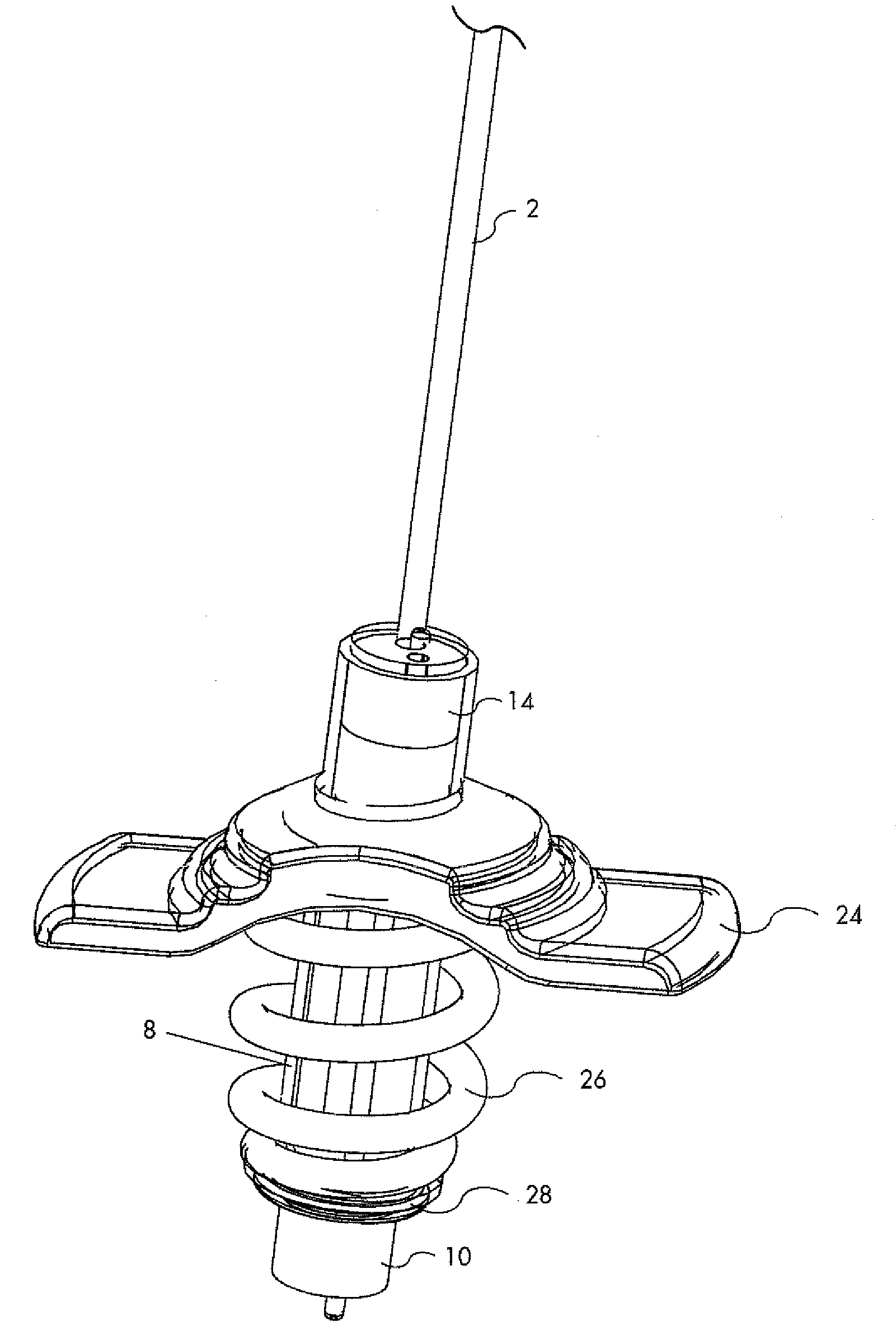
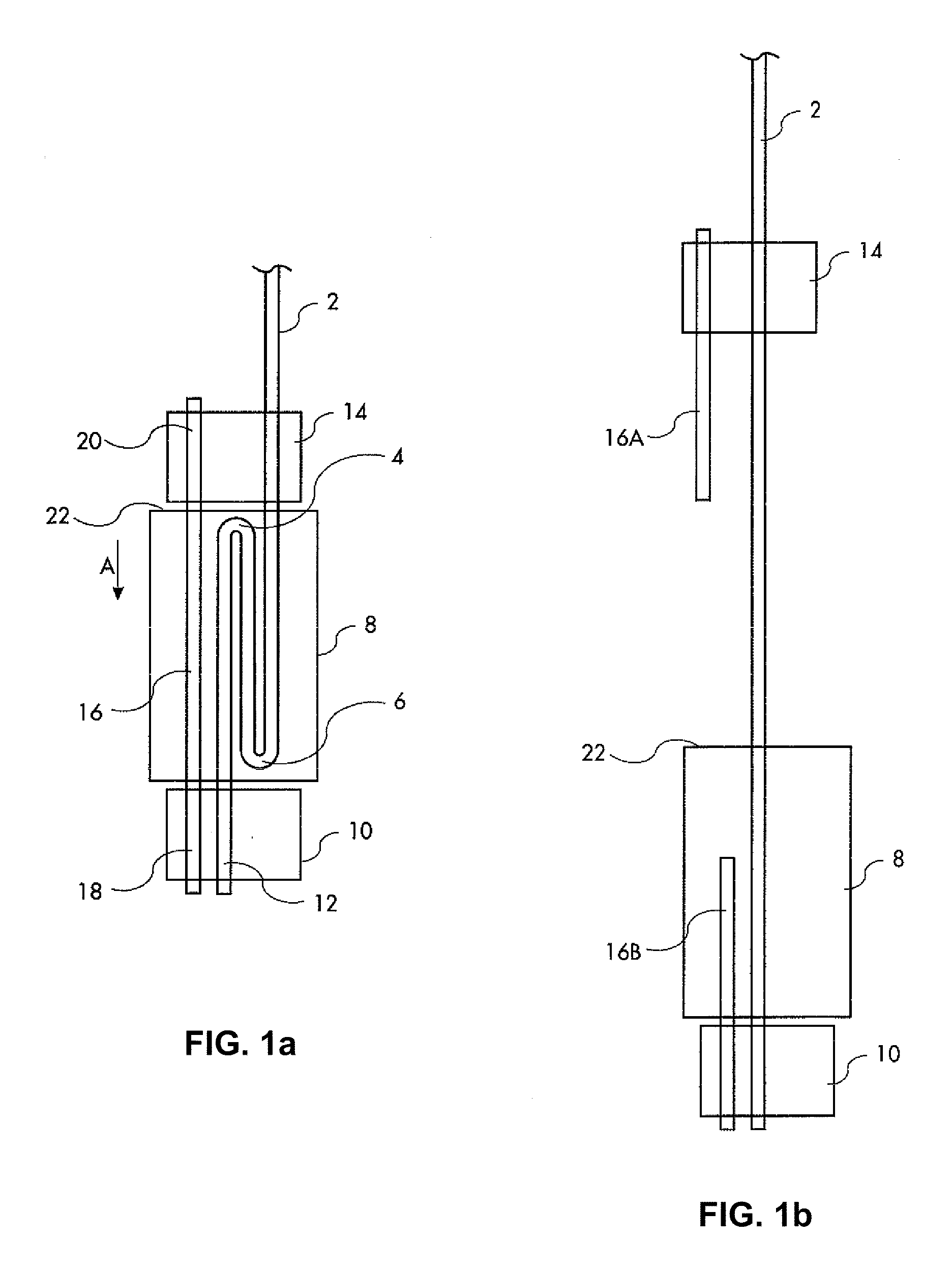
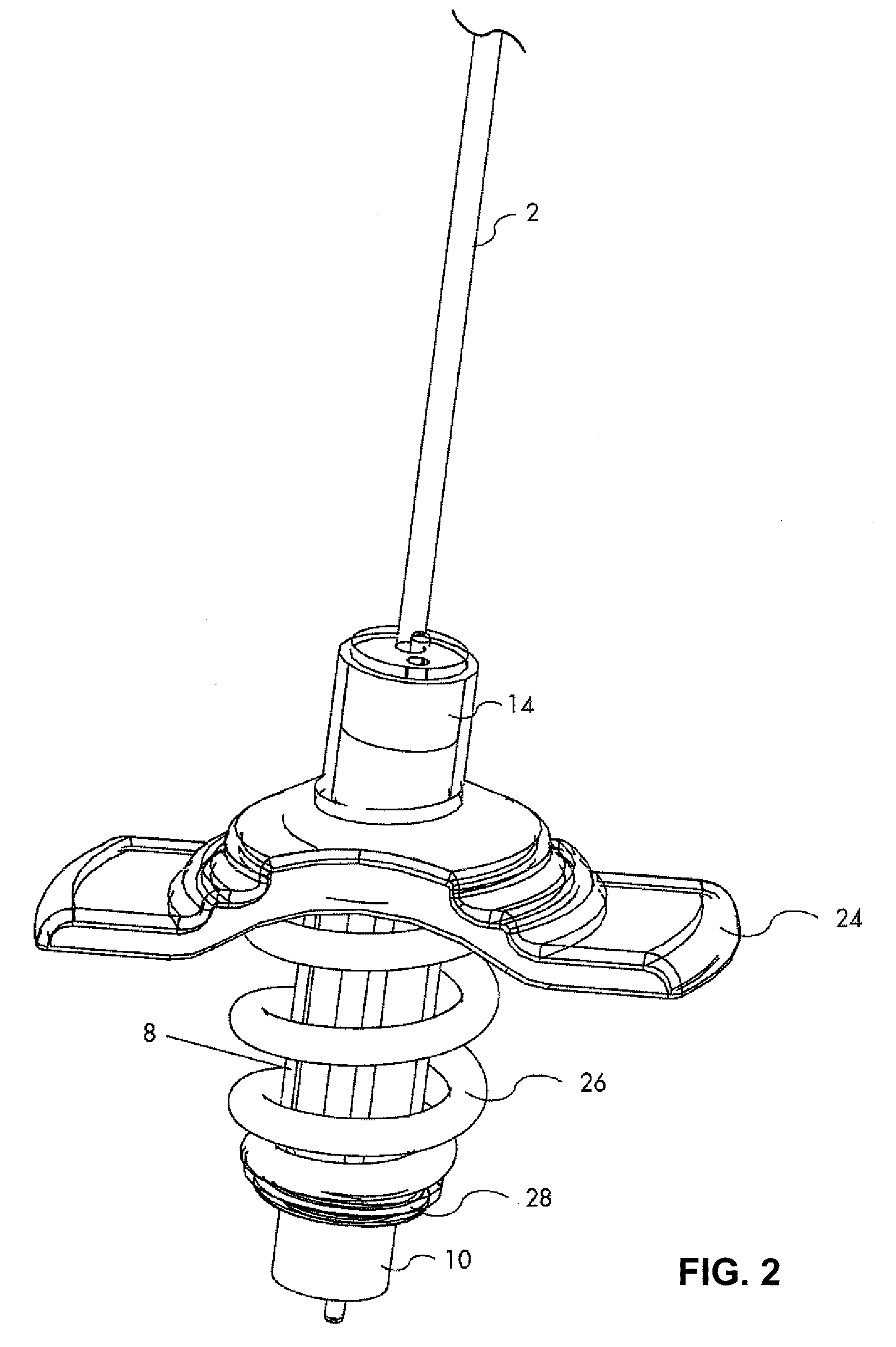
[0017]Referring now to the drawings, there is shown in FIG. 1a a schematic description of the device according to the present invention, at normal operation. A first cable 2 (constituting a hoisting cable) has a first folding 4 and a second folding 6 accommodated in a hollow cylinder 8. Cable 2 is tightly fastened in a lower ferrule 10 at the cable's object end 12 and in an upper ferrule 14 along its length above cylinder 8. A second short cable 16 (constituting an auxiliary cable) is also tightly fastened at its lower end 18 and at its upper end 20 in ferrules 10 and 14, respectively. Instead of folding the cable 2 inside ferrule 10, the cable may just as well be coiled therein.

[0018]In the event of a severe shock applied to the upper end 22 of the cylinder 8 by spare tire 23 (shown in ...


PUM


Abstract

A device for absorbing shocks of a liftable and lowerable object such as a spare tire includes a first hoisting cable having a hoist-side end and an object-side end and a hollow cylinder encompassing a folded or coiled length of the first hoisting cable near the object end inside the cylinder. Lower and upper ferrules at the lower and upper ends of the cylinder are held in position by a second auxiliary cable having two ends, each end attached to one of the ferrules, the second auxiliary cable having a smaller tearing strength than the first hoisting cable.

Description

FIELD OF THE INVENTION[0001]The present invention relates to a device for securing a lowerable and liftable object, in particular, a spare tire for a vehicle against disconnection from the vehicle during or following accidents, crashes or severe shocksBACKGROUND OF THE INVENTION[0002]Spare tires for vehicles are mostly heavy and bulky objects that, in many vehicles, are accommodated below the vehicle body and are secured against the bottom of the vehicle or against a structure carried by elements of the vehicle chassis. Because of their weight and size, vehicle spare tires can rarely be lowered to the ground, nor raised for storage, by hand. For this reason, heavier vehicles are provided with hoisting devices such as winches, by means of which the spare tire is lowered or raised using a steel cable.[0003]Steel cables, however, are liable to snap or break due to a number of causes, all of which are relevant to their use for the above-mentioned purpose: lack of maintenance, corrosion ...

Claims


Application Information

Patent Timeline
IPC IPC(8): B62D43/04B66D1/40
CPCB66C1/12B62D43/045
Inventor KHAVRONINE, ALEXANDRE
Owner MAG USA INC
Why Eureka
Try Eureka