
System and method for traffic related information display, traffic surveillance and control

a technology of traffic related information and display system, applied in the field of display system, can solve problems such as serious violations or accidents, and achieve the effects of simple, reliable, clear, and long operation li

Inactive Publication Date: 2009-10-15
HAKKI A HAMID +3
View PDF24 Cites 44 Cited by
  • Summary
  • Abstract
  • Description
  • Claims
  • Application Information

AI Technical Summary

Benefits of technology

[0024]It is therefore an object of the present invention to provide a system for traffic surveillance, control, and display of traffic conditions as well as other suitable parametric information for vehicle's occupants and pedestrians. Such provides simple, reliable, clear and easily understandable visual messages, which enjoy low energy requirements, long operational life, and low maintenance profiles.
[0025]It is also an object of the present invention to provide a processor-based efficient traffic surveillance, control, and traffic information display system which permits prediction of a probable accident based on deceleration of vehicles and which displays the traffic condition on predefined portions of the road which may influence the intended trajectory of travel of vehicles and pedestrians.
[0026]It is a still further object of the present invention to provide a traffic information display system which enhances regulation of traffic in an efficient manner by providing the information regarding speed of vehicles, traffic jams, delays, etc. at a given intersection to other traffic displays at roads connected to the given intersection or which may be influenced by the traffic condition thereat.

Problems solved by technology

If a vehicle did not clear the intersection and a predetermined time has elapsed after the change to red color, a serious violation or an accident has occurred.

Method used


Image

  • System and method for traffic related information display, traffic surveillance and control
  • System and method for traffic related information display, traffic surveillance and control
  • System and method for traffic related information display, traffic surveillance and control

Examples


Embodiment Construction

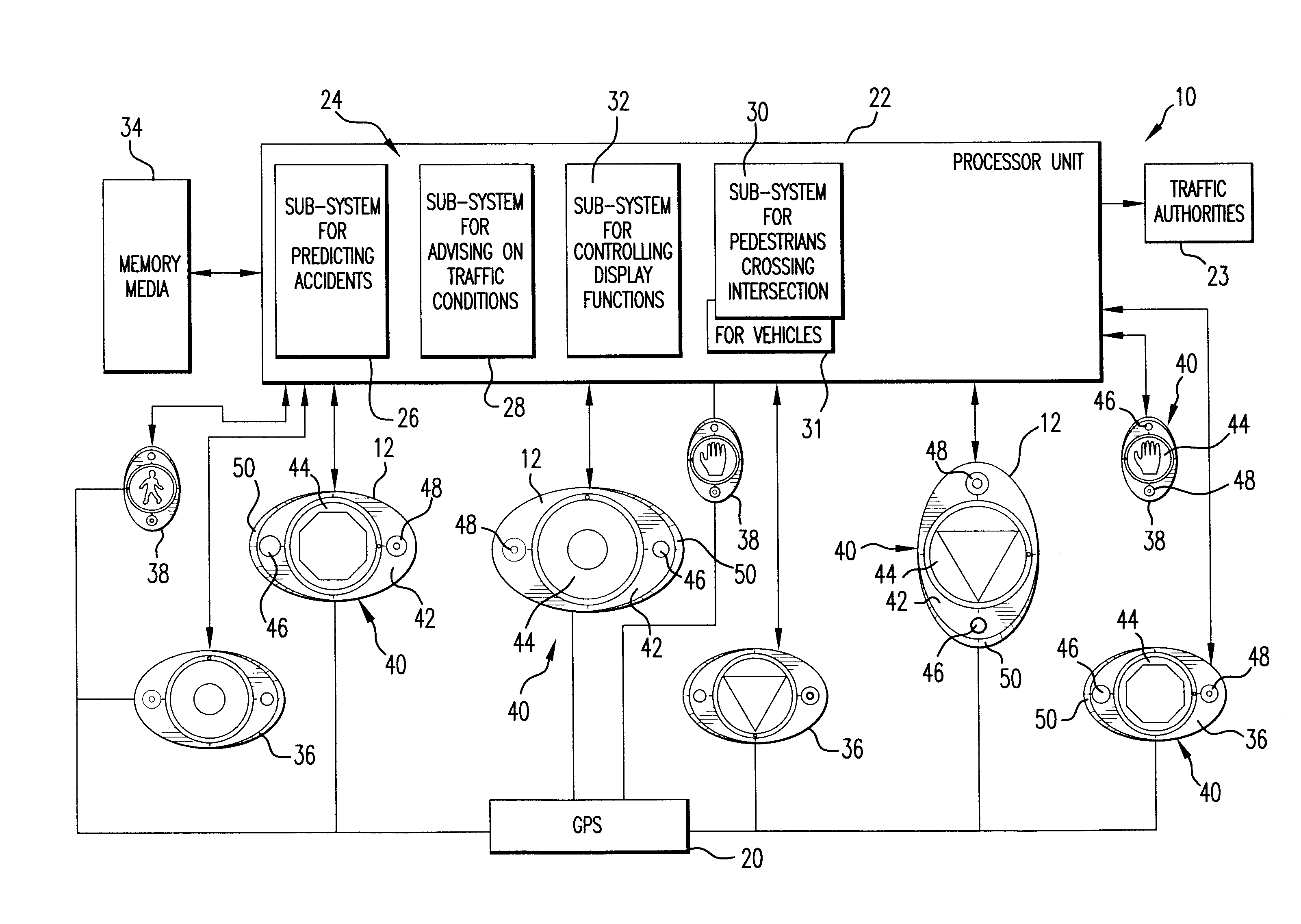
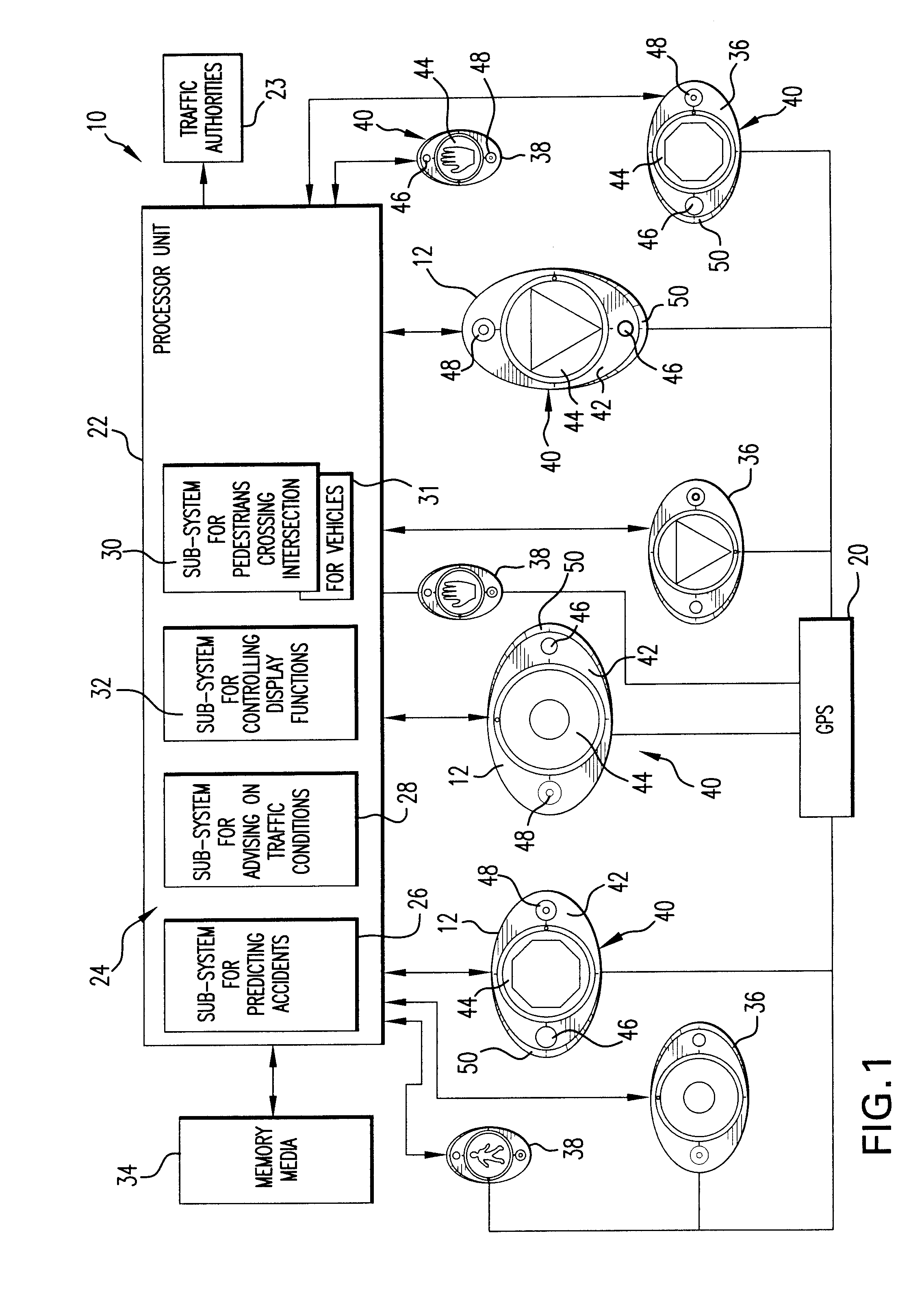
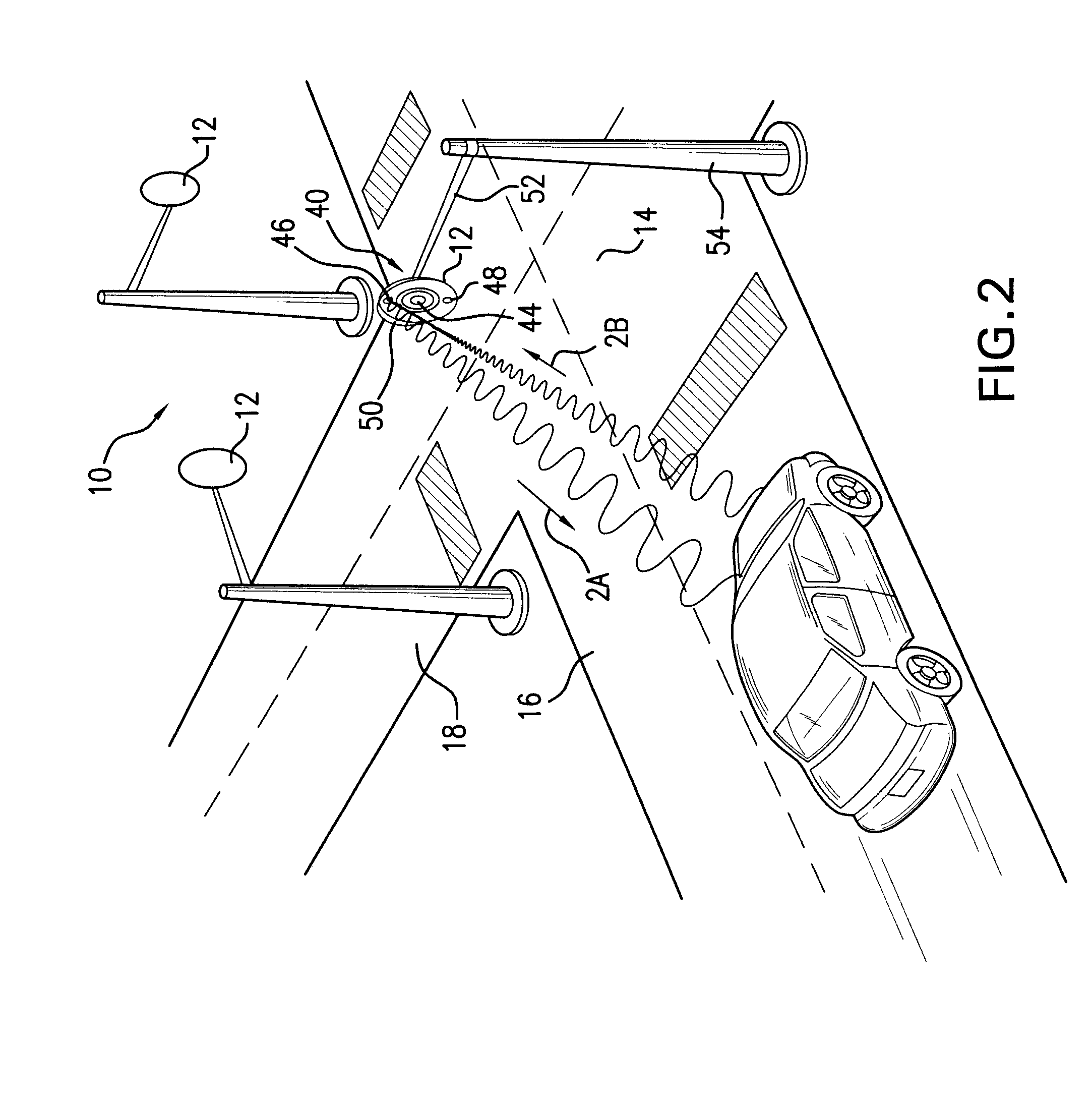
[0076]Referring to FIGS. 1, 2 and 8 a system 10 for traffic surveillance, control, and traffic related information display is shown which includes a plurality of display units 12 positioned at predetermined locations along the traffic flow. The system 10 of the present invention may also be called a Traffic Entry Display and Surveillance System, or TEDS system. The display units 12 may be located at intersections 14 as shown in FIGS. 2 and 8. It should be readily available for those skilled in the art that, although being shown as positioned at the intersection 14, the display units 12 of the present invention may be positioned at any location along the road 16, 18. The coordinate of each display unit 12 is assigned by a GPS (Global Positioning System) 20. Each display unit 12 is connected to a processor unit 22 (Central Processing Unit) which receives information from the display units 12, processes and analyzes the information, and issues signals transmitted to the display units 1...


PUM


Abstract

The system and method for traffic surveillance, control, and traffic related information display uses display units each having display element sensors and cameras where the operation is controlled by a processor. Anticipatory sensor systems continuously measure speed and deceleration of approaching vehicles, sends signals to the processor which in turn analyzes the incoming signals. A rapid sequence camera continuously records audio-video images. When the rate of deceleration exceeds a predetermined threshold, which may be indicative of an imminent accident, the processor activates a store regime of the audio visual images on-site or transmitted to an off-site location for further actions. The information on the traffic flow condition which may affect the vehicle travel is displayed on the display unit. The system provides for the detection of pedestrians about to cross an intersection and controls the traffic light pattern accordingly. The display unit utilizes shapes, motions, and color to provide for easily understandable messages to vehicle occupants and pedestrians.

Description

RELATED APPLICATIONS[0001]This application is a Continuation of U.S. application Ser. No. 11 / 232,917 filed 23 Sep. 2005.FIELD OF THE INVENTION[0002]The present invention relates to a display system designed to demonstrate simple, reliable, clear, and universally understandable visual messages, for vehicles' occupants and pedestrians to aid in optimizing the efficiency of traffic flow as well as to increase safety considerations of people on the roadways.[0003]It is another object of the present invention to provide a traffic control system measuring and analyzing traffic related data, and displaying the data in clearly understandable forms to provide vehicle occupants, as well as pedestrians, with information regarding speed of vehicles, traffic jams, or car accidents at a given portion of the road.[0004]The present invention additionally relates to a traffic control system which predicts an eminent accident by calculating the rate of deceleration of vehicles approaching the interse...

Claims


Application Information

Patent Timeline
Patent Type & Authority Applications(United States)
IPC IPC(8): H04N7/18G08G1/08
CPCG08G1/0175G08G1/164G08G1/081G08G1/005
Inventor HAKKI, A-HAMIDHAKKY, SAIDHAKKI, SAMHAKKI, HADI
Owner HAKKI A HAMID
Learn More