Al technical title is built by PatSnap Al team. It summarizes the technical point description of the patent document.
a technology of seismic event detection and method, applied in the field of systems for detecting seismic movements, to achieve the effect of fast and efficient implementation or positioning
Inactive Publication Date: 2009-10-15
CHERRY J THEODORE
View PDF6 Cites 4 Cited by
Summary
Abstract
Description
Claims
Application Information
AI Technical Summary
This helps you quickly interpret patents by identifying the three key elements:
Problems solved by technology
Method used
Benefits of technology
[0011]Therefore, a need has arisen for seismic event detection systems and methods of employing such seismic event detection systems that overcome these and other shortcomings of related art systems and methods. A technical advantage of embodiments of the present invention is that the seismic event detection systems may be wholly or substantially portable, implanted or positioned quickly, efficiently, and, if necessary, covertly, and are adaptable to changing needs and conditions. Further, these systems may detect precursors, which may be lower in magnitude than the seismic events that succeed them. An earthquake precursor may be a seismic event or series of related events that appear and are detectable prior to a larger scale seismic event, e.g., an earthquake. A precursor may be identified by searching for seismic events having similar fundamental characteristics to larger seismic events. By detecting, measuring, and analyzing these precursors, the location and magnitude of earthquakes may be predicted in advance.
Problems solved by technology
Further, these systems may detect precursors, which may be lower in magnitude than the seismic events that succeed them.
Method used
Image
Click on the blue label to locate the original text in one second.
Reading with bidirectional positioning of images and text.
Examples
Embodiment Construction
[0028]Preferred embodiments of the present invention and their advantages may be understood by referring to FIGS. 1-10, like numerals being used for like corresponding parts in the various drawings.
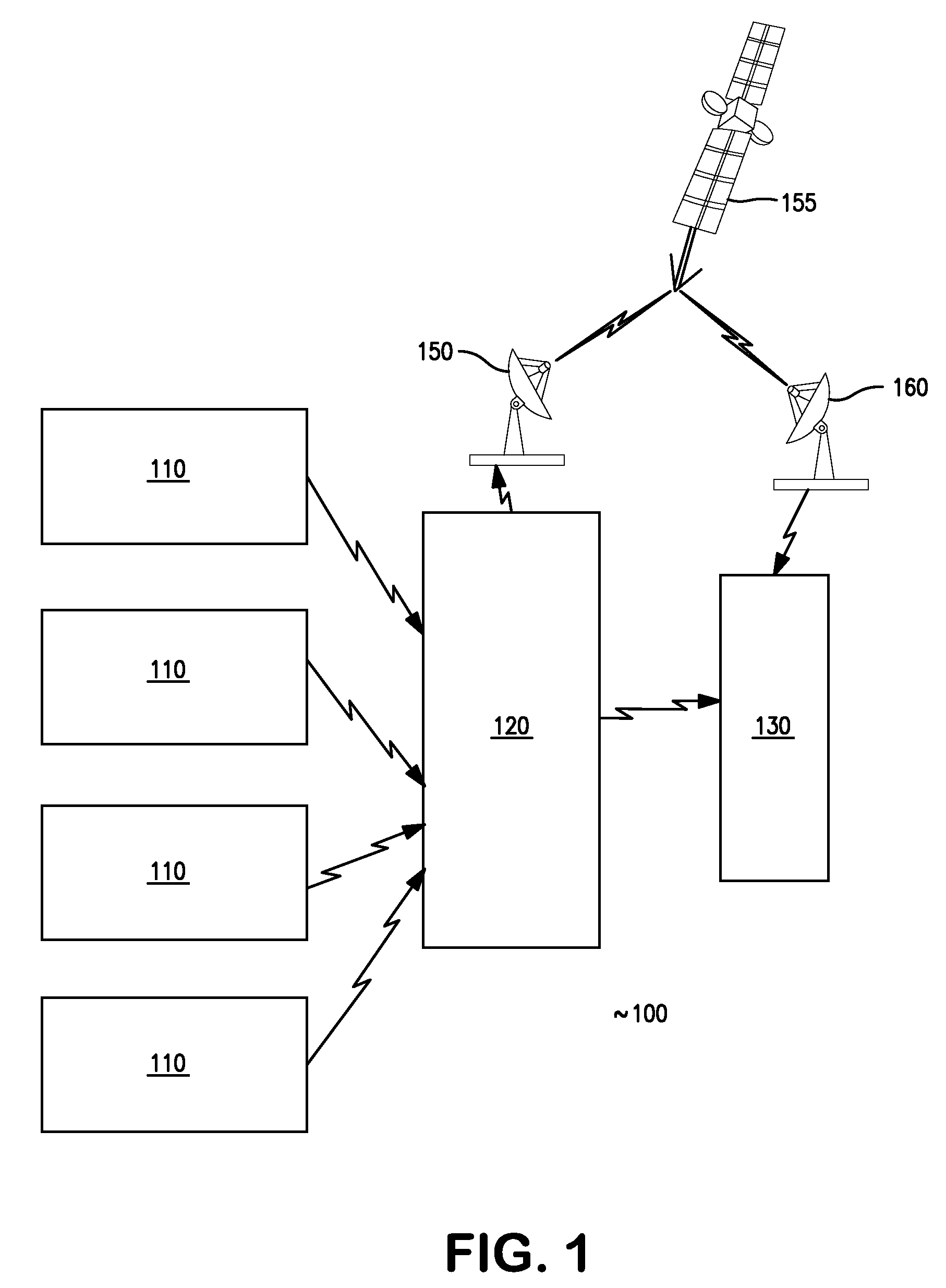
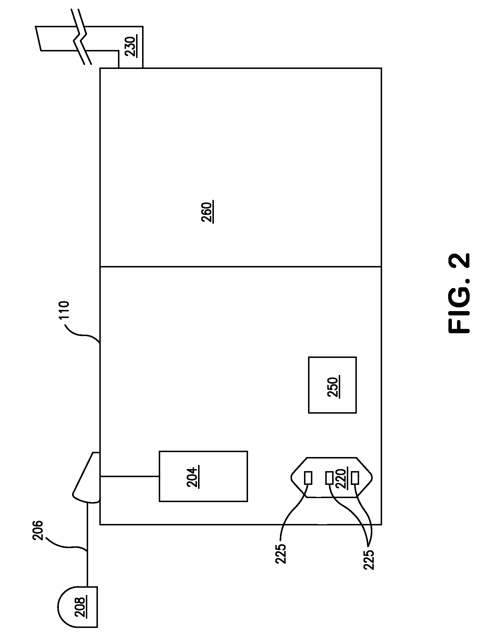
[0029]Referring to FIG. 1, a system 100 for detecting seismic events may comprise a plurality of sensor modules, e.g., seismic sensors including seismometers, infrasound sensors, hydroacoustic sensors, or other sensors. In an embodiment of the invention, between two (2) and about twenty (20) sensor modules 110 (described herein with respect to FIG. 2) may be incorporated into the system. Nevertheless, a single sensor could be used at a single site. In an embodiment of the invention, four (4) sensor modules 110 provide sufficient data to extrapolate meaningful results, without overloading the system with data points. System 100 also may comprise a communications interface module, e.g., communications interface module 120. In an embodiment described herein, communications interface module 1...
PUM
Abstract
The invention is directed to a system for detecting seismic waves. The system has one or more sensor modules. Each sensor module has a detection unit, a positioning module, a digitizer, a radio transmitter, and a power supply. The system also includes a communications interface including a receiver, a data storage device, and a data relay module, and a data processor. The system may be used to detect seismic events by positioning sensor modules in an area, positioning a communications interface module in an area, establishing communication, polling the sensor modules for data, and relaying the data. The polling and relaying may be repeated at predetermined time intervals. Then, analysis may be performed on the data, and the seismic event may be identified as a precursor.
Description
CROSS-REFERENCE TO RELATED APPLICATIONS[0001]The present application claims priority to and is a divisional application of patent application Ser. No. 12 / 120,800, filed on May 15, 2008, which application claims the benefit of the provisional application entitled “METHODS AND SYSTEMS FOR SEISMIC EVENT DETECTION,” Provisional Patent Application No. 60 / 924,546, filed on May 18, 2007, the provisional application entitled “METHODS AND SYSTEMS FOR SEISMIC EVENT PREDICTION,” Provisional Patent Application No. 60 / 935,453, filed on Aug. 14, 2007, and the provisional application entitled “INSTANTANEOUS SEISMIC EVENT PREDICTION AND DETECTION,” Provisional Patent Application No. 60 / 984,245, filed on Oct. 31, 2007. The disclosures of each of patent application Ser. No. 12 / 120,800 and Provisional Patent Application Nos. 60 / 924,546, 60 / 935,453, and 60 / 984,245, are incorporated herein by reference in their entirety.BACKGROUND OF THE INVENTION[0002]1. Field of the Invention[0003]The invention relate...
Claims
Application Information
Patent Timeline
Application Date:The date an application was filed.
Publication Date:The date a patent or application was officially published.
First Publication Date:The earliest publication date of a patent with the same application number.
Issue Date:Publication date of the patent grant document.
PCT Entry Date:The Entry date of PCT National Phase.
Estimated Expiry Date:The statutory expiry date of a patent right according to the Patent Law, and it is the longest term of protection that the patent right can achieve without the termination of the patent right due to other reasons(Term extension factor has been taken into account ).
Invalid Date:Actual expiry date is based on effective date or publication date of legal transaction data of invalid patent.
Patent Type & Authority Applications(United States)