Scene based non-uniformity correction systems and methods

a non-uniformity correction and scene technology, applied in the field of infrared imaging systems, can solve the problems of inability to accurately detect the image, generate the image, and the dominant source of noise may result from fixed pattern noise (fpn), and achieve the effect of reducing fixed pattern nois

Active Publication Date: 2009-10-15
TELEDYNE FLIR LLC
View PDF7 Cites 58 Cited by
  • Summary
  • Abstract
  • Description
  • Claims
  • Application Information

AI Technical Summary

Benefits of technology

[0006]Systems and methods are disclosed herein to provide scene-based non-uniformity correction for an infrared image (e.g., from a microbolometer sensor of an infrared imaging system), in accordance with one or more embodiments. For example, in accordance with an embodiment of the present disclosure, a method of processing infrared images includes storing a template frame comprising a first plurality of pixel data of an infrared image; receiving an input frame comprising a second plurality of pixel data of an infrared image; determining frame-to-frame motion between at least some of the first and second plurality of pixel data; warping the template frame based on the determining of the frame-to-frame m

Problems solved by technology

An image generated by an infrared imager, such as for example a microbolometer-based infrared imager, typically includes noise.
For example, the dominant source of noise may result from fixed pattern noise (FPN), particularly for uncooled microbolometer imagers.
For example, FPN may be barely noticeable or it may cause severe distortion of the image to the point that the video is no longer useful.
In practice, this has proven difficult and systems generally use an internal shutter that lets the system acquire an image against a uniform target to calibra

Method used


Image

  • Scene based non-uniformity correction systems and methods
  • Scene based non-uniformity correction systems and methods
  • Scene based non-uniformity correction systems and methods

Examples


Embodiment Construction

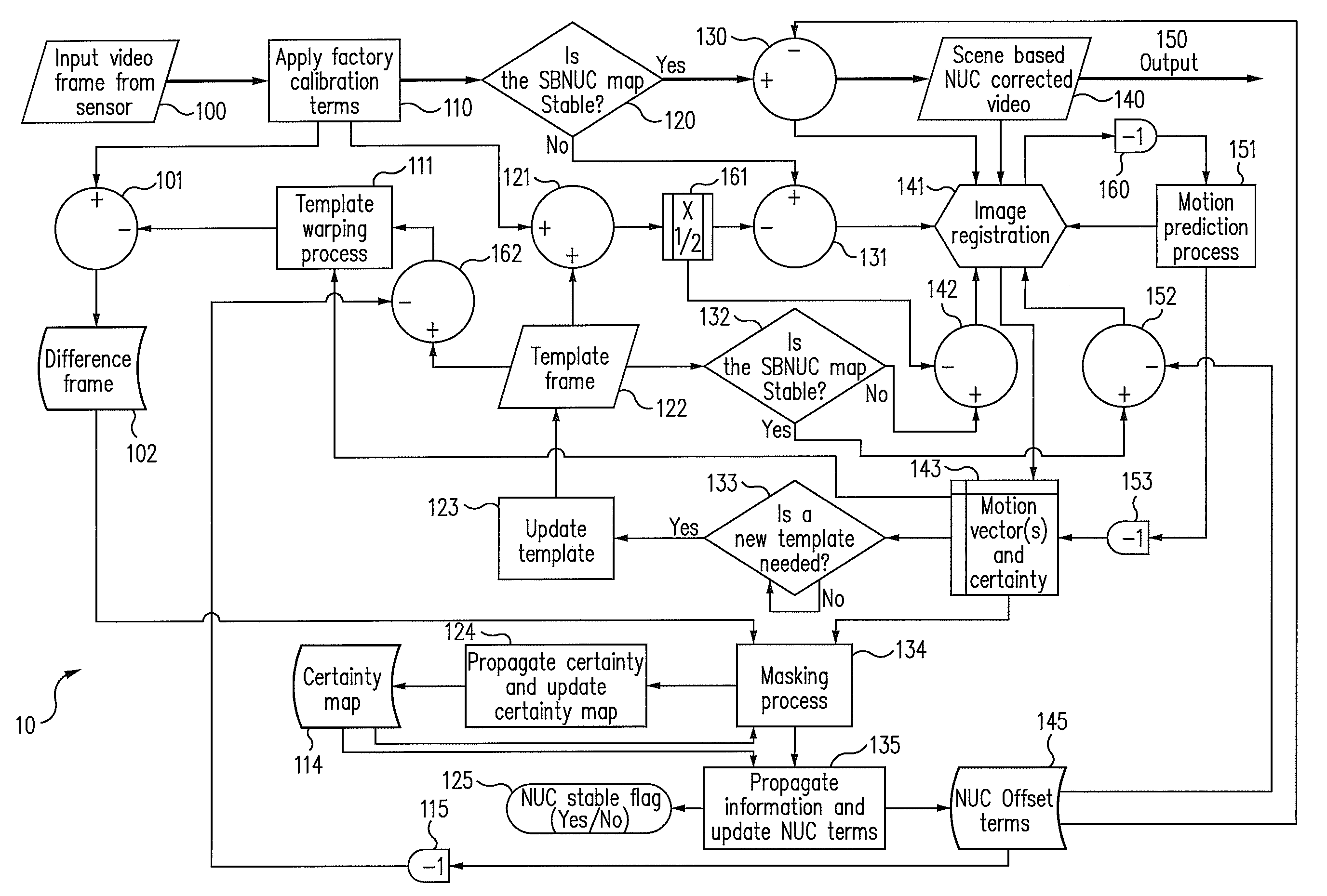
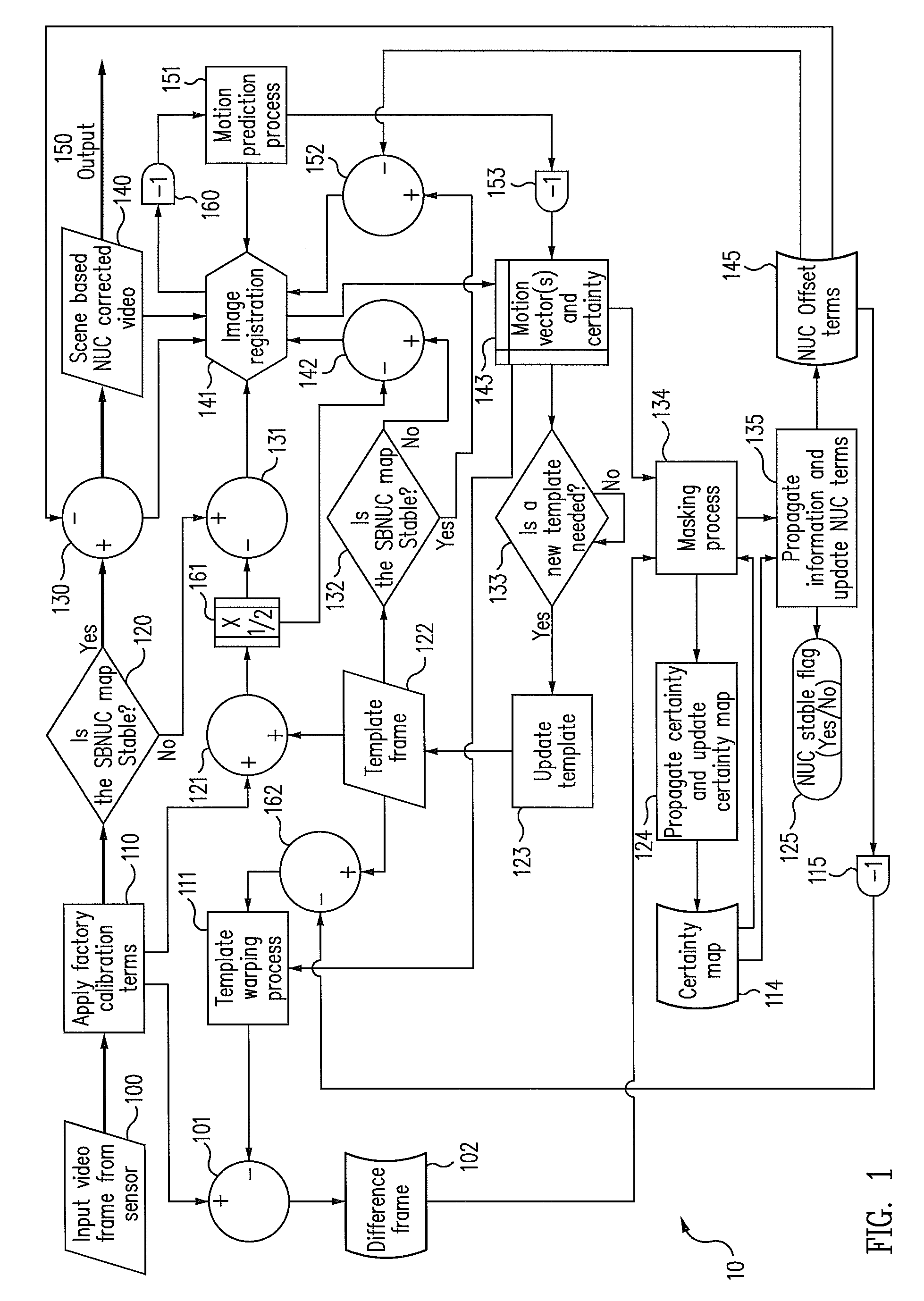
[0020]FIG. 1 illustrates a block diagram of an algorithm 10 to perform non-uniformity correction (NUC) on infrared image data. Algorithm 10 may perform NUC based on information contained within the infrared image data of the scene being imaged and may be referred to as scene-based NUC (SBNUC). For example, algorithm 10 may provide SBNUC for a system that captures multiple images (e.g., image frames) of the scene over time, for example video images generally of a scene from an infrared camera.

[0021]In an example embodiment, algorithm 10 may be based on certain principals. For example, the scene irradiance may be assumed to be static over a number of frames (e.g., at least two frames), while the FPN may be assumed to be static over a larger number of frames (e.g., on the order of a hundred frames). The algorithm may also assume that there is some movement relative to the sensor from frame to frame, even where the camera is stationary.

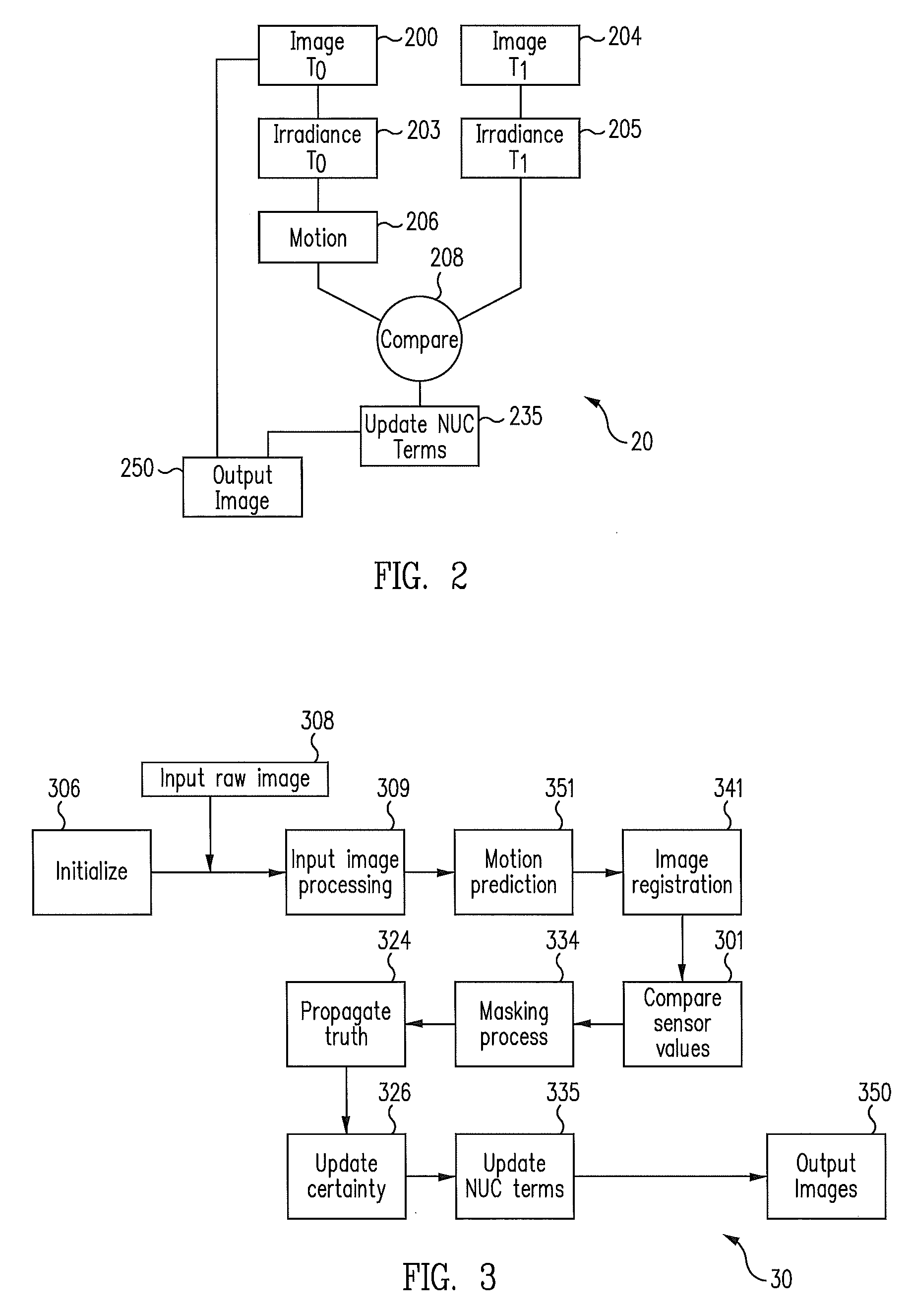
[0022]As a specific example, referring briefly to F...


PUM


Abstract

Systems and methods provide scene-based non-uniformity correction for infrared images, in accordance with one or more embodiments. For example in one embodiment, a method of processing infrared images includes storing a template frame comprising a first plurality of pixel data of an infrared image; receiving an input frame comprising a second plurality of pixel data of an infrared image; determining frame-to-frame motion between at least some of the first and second plurality of pixel data; warping the template frame based on the determining of the frame-to-frame motion; comparing the first plurality of pixel data to the second plurality of pixel data to determine irradiance differences based on the determining; propagating pixel offset information for scene based non uniformity correction terms, based on the determining of the frame-to-frame motion, for at least some of the scene based non uniformity correction terms to other ones of the scene based non uniformity correction terms; updating the scene based non uniformity correction terms based on the comparing and the propagating; applying the scene based non uniformity correction terms to the second plurality of pixel data to reduce fixed pattern noise; and providing an output infrared image after the applying.

Description

TECHNICAL FIELD[0001]The present invention relates generally to an infrared imaging system and, more particularly, to systems and methods for processing infrared image data.BACKGROUND[0002]An image generated by an infrared imager, such as for example a microbolometer-based infrared imager, typically includes noise. For example, the dominant source of noise may result from fixed pattern noise (FPN), particularly for uncooled microbolometer imagers. The source of FPN may be due, for example, to non-linearity of sensor elements, reflections inside the camera, temperature gradients within the system, non-linearity of the electronics, particles or water on the lens in front of the shutter, and / or a non-uniform temperature of the shutter (e.g., if not completely defocused). The source of the FPN may, at least in part, determine the appearance of the FPN in the image, with uncooled imagers typically having a higher portion of low spatial frequency FPN than cooled cameras.[0003]In general, ...

Claims


Application Information

Patent Timeline
IPC IPC(8): G06K9/40
CPCG06T5/50H04N5/3656H04N5/33H04N25/674
Inventor HOGASTEN, NICHOLAS
Owner TELEDYNE FLIR LLC
Why Eureka
Try Eureka