Method for joining strips, structure of joint, and continous strip obtained by the method

a technology of pressure-sensitive adhesive tape and structure, applied in the direction of film/foil adhesives without carriers, photosensitive materials, instruments, etc., can solve the problems of reducing productivity, insufficient peeling workability, and continuous strip composed of strips joined, so as to achieve superior workability and productivity.

Inactive Publication Date: 2009-10-15
NITTO DENKO CORP
View PDF7 Cites 3 Cited by
  • Summary
  • Abstract
  • Description
  • Claims
  • Application Information

AI Technical Summary

Benefits of technology

[0007]Accordingly, an object of the present invention is to provide a method for joining strips each including a laminate of a release liner and a pressure-sensitive adhesive layer, to give a continuous strip which does not cause an edge of a release liner at the joint portion upon removal or peeling of the release liner from the continuous strip, and which is superior in workability and productivity. Another object of the present invention is to provide a joint structure formed by the method; and a continuous strip composed of strips joined by the method.
[0008]After intensive investigations to achieve the objects, the present inventors have found that the occurrence of the edge of the release liner at the joint portion upon removal of a release liner from the continuous strip can be prevented by allowing a release liner in an end region of at least one of object two strips to extend from the corresponding pressure-sensitive adhesive layer; and superposing and fixing the release liners so that the surfaces of the release liners in portions of a predetermined length from a longitudinal end are not in contact with the surfaces of the pressure-sensitive adhesive layers. The present invention has been made based on these findings.
[0019]Continuous strips formed by joining strips by any of these methods do not suffer from the occurrence of an edge of a release liner, which causes “binding (or catch)”, at the joint portion upon removal of the release liner therefrom. The workability and productivity in processes using the continuous strips are thereby improved.

Problems solved by technology

The resulting continuous strip (pressure-sensitive adhesive tape) composed of strips joined by the above method, however, suffers from problems when the release liners are removed from the pressure-sensitive adhesive tape upon use.
Thus, the peeling workability is insufficient, or the release liner breaks to reduce the productivity.
Additionally, there occur problems in product quality.
Typically, the increased peel force at the edge portion causes a crevice in the joint between the pressure-sensitive adhesive layers, and sealing at the joint portion becomes insufficient.

Method used


Image

  • Method for joining strips, structure of joint, and continous strip obtained by the method
  • Method for joining strips, structure of joint, and continous strip obtained by the method
  • Method for joining strips, structure of joint, and continous strip obtained by the method

Examples


example 1

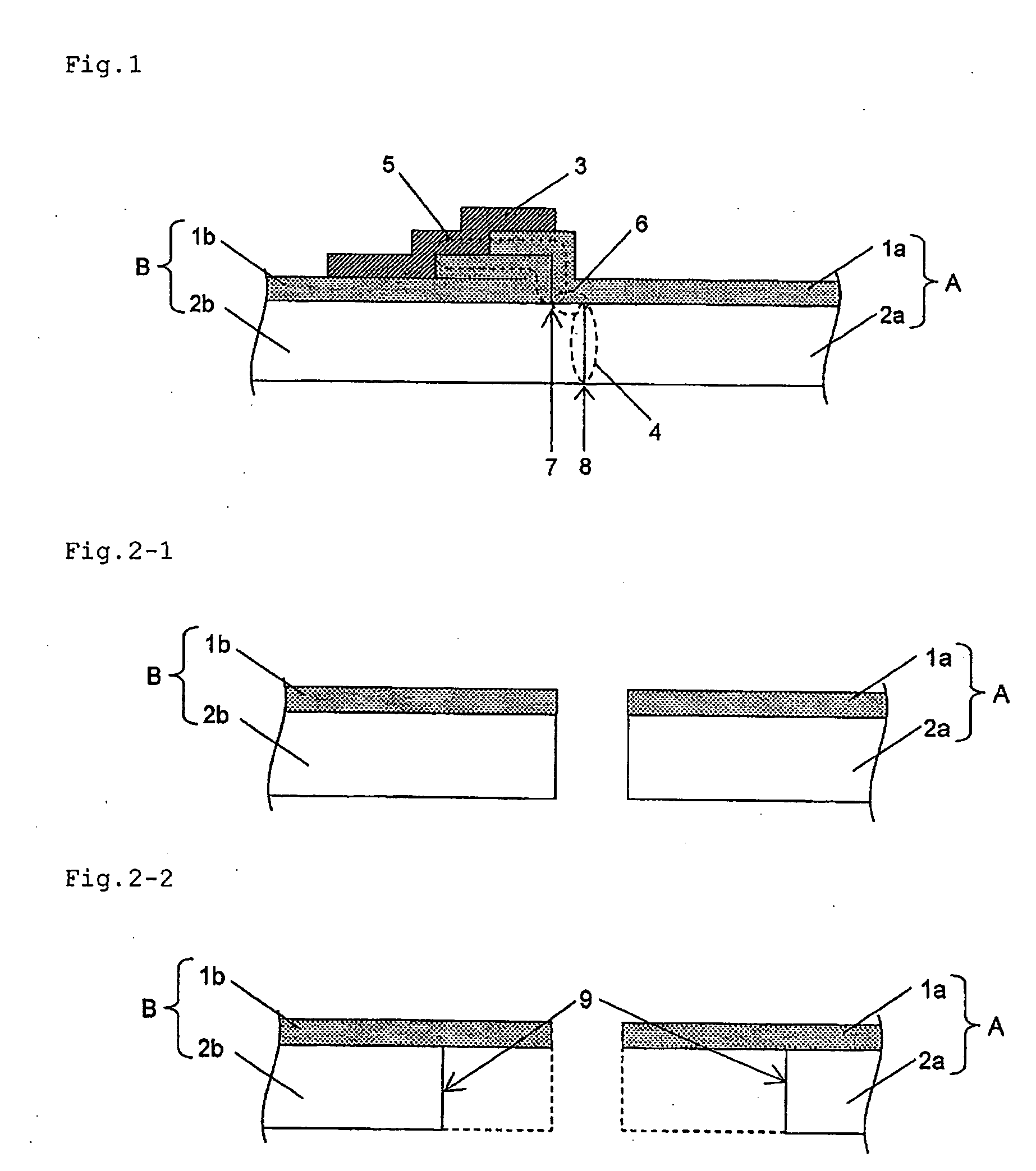
[0087]Two double-sided acrylic foam adhesive tapes were joined by the method illustrated in FIGS. 2-1 to 2-4.

[0088]In the step in FIG. 2-2, the pressure-sensitive adhesive layer of one of the two tapes (strip B in FIG. 2-2) was not removed, and the pressure-sensitive adhesive layer of the other tape (strip A in FIG. 2-2) was cut and removed to a length of 15 mm from its end.

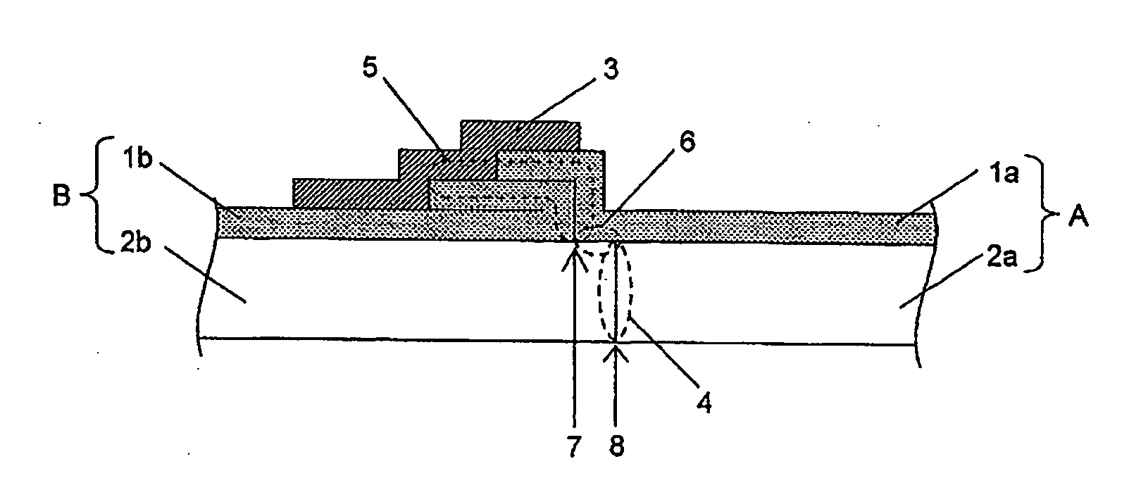
[0089]Next, with reference to FIG. 2-3, the pressure-sensitive adhesive layers were bonded by butting end cross-sections of the pressure-sensitive adhesive layers against each other. End regions of the release liners were brought at least partially into contact with each other so as to allow their sides having been faced the pressure-sensitive adhesive layers to face each other to form a superposed portion, so that the release liner 1a of the tape A lied on the pressure-sensitive adhesive layer 2b of the tape B by a length of 12 mm. In the front end region of the faced release liners, the tip of release liner 1b ...

example 2

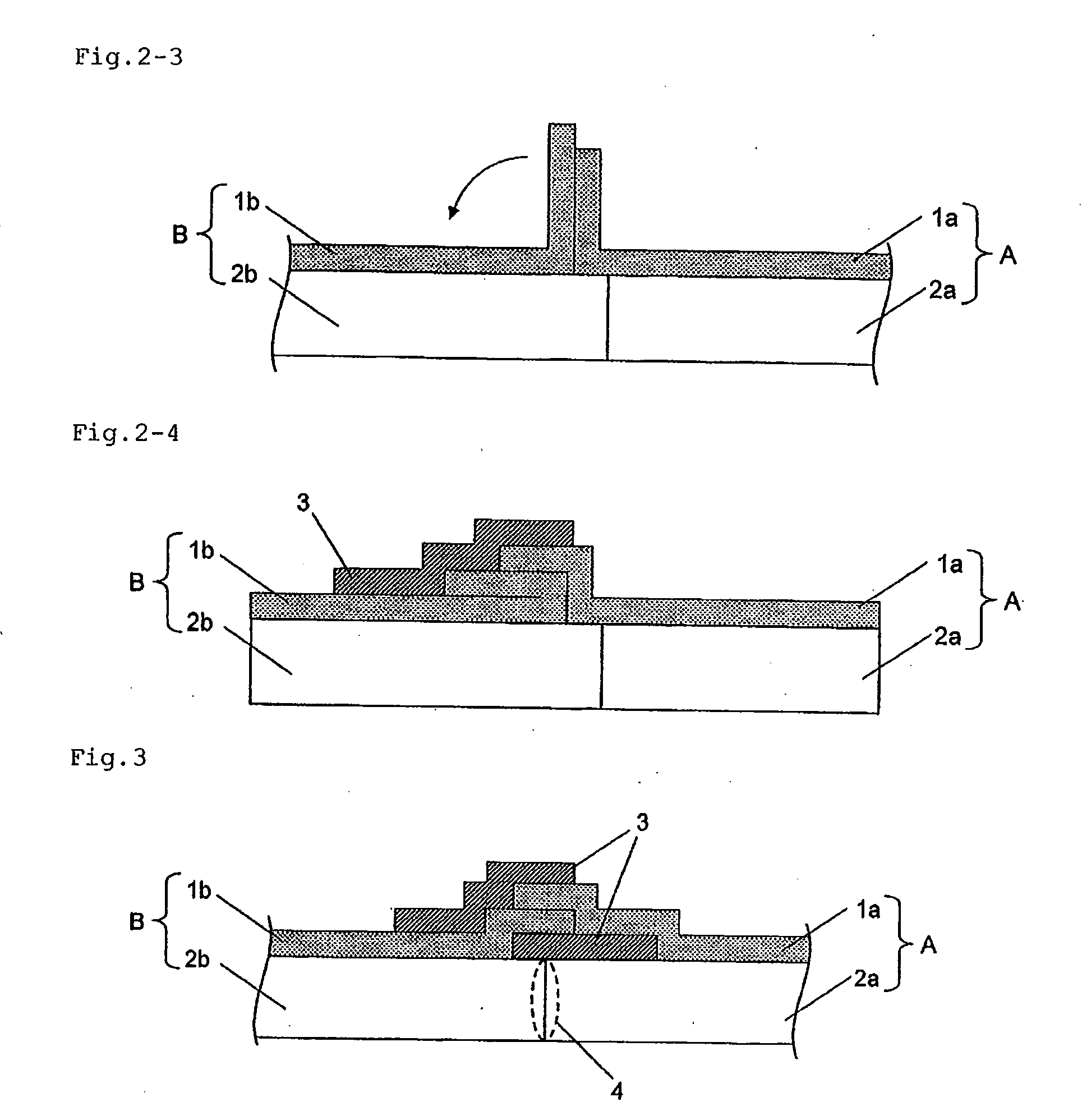
[0093]Two double-sided acrylic foam adhesive tapes were joined by the method illustrated in FIG. 3. The pressure-sensitive adhesive layer of one of the two tapes (strip B in FIG. 3) was cut and removed from its end by a length of 5 mm, and the pressure-sensitive adhesive layer of the other tape (strip A in FIG. 3) was not removed.

[0094]Next, with reference to FIG. 3, the pressure-sensitive adhesive layers were bonded by butting their end cross-sections against each other. The release liners were superposed so that one release liner (1a) partially lied on the other release liner (1b) to form a superposed portion; the superposed portion was fixed by applying the same joint tape (20 mm long and 6 mm wide) as in Example 1 to the upper and lower sides of the superposed portion, to form a joint to thereby join the two double-sided acrylic foam adhesive tapes. The superposed portions of the release liners had a length of 5 mm.

[0095]Thus, a continuous double-sided acrylic foam adhesive tape...


PUM

PropertyMeasurementUnit
lengthaaaaaaaaaa
lengthaaaaaaaaaa
lengthaaaaaaaaaa

Abstract

Disclosed is a method for joining two strips, where the two strips each include a laminate of a release liner and a pressure-sensitive adhesive layer, and the release liner extends from the corresponding pressure-sensitive adhesive layer in a longitudinal end region of at least one of the two strips. The method includes butting cross-sections of longitudinal ends of the pressure-sensitive adhesive layers of the two strips to bond the two pressure-sensitive adhesive layers; and superposing end regions of the release liners of the two strips and fixing the release liners so that surfaces of the release liners in portions at least 1 mm long inward from the longitudinal ends are not in contact with surfaces of the pressure-sensitive adhesive layers. This method gives a continuous strip from which the release liner can be smoothly removed without “binding” even at the joint.

Description

BACKGROUND OF THE INVENTION[0001]1. Field of the Invention[0002]The present invention relates to a method for joining two strips each including a laminate of a release liner and a pressure-sensitive adhesive layer. It relates also to the structure of a joined portion (joint) formed by the method, and to a continuous strip composed of two or more strips joined by the method.[0003]2. Description of the Related Art[0004]Strips each including a pressure-sensitive adhesive layer and a release liner (such as pressure-sensitive adhesive tapes) are used in a variety of fields (typically see Japanese Unexamined Patent Application Publication (JP-A) No. 2007-217553 corresponding to US20070190280A). During manufacture of strips, the strips are joined with each other typically when a failed portion, if occurring, is removed and the residual portions are joined to give a product, or when short-length strips are joined to give a long (continuous) product.[0005]Of these strips, pressure-sensitive ...

Claims


Application Information

Patent Timeline
Patent Type & Authority Applications(United States)
IPC IPC(8): B32B3/00B32B37/00C09J7/10
CPCC09J7/00C09J7/0232C09J2201/128Y10T428/192C09J2201/606C09J2423/005Y10T428/195C09J2201/36C09J7/403C09J7/10C09J2301/208C09J2301/124C09J2301/302
Inventor KOSAKA, TOKUHISAMAMIYA, MASATOSHIHIROSE, ISAOINOKUCHI, SHINJI
Owner NITTO DENKO CORP
Why Eureka
Try Eureka