
Apparatus ans method for aligning and/or stabilizing the spine

a technology of spinal vertebrae and apparatus, which is applied in the field of apparatus for aligning and/or stabilizing the spinal vertebrae, can solve the problems of difficulty in the surgeon's attachment of the screws heads to the rods, the problem of the transfer of the load normally carried by the spinal column to the stabilizer through the connection between the rod and the screw, and the absence of prior art devices

Inactive Publication Date: 2009-10-15
PERUMALA CORP
View PDF7 Cites 88 Cited by
  • Summary
  • Abstract
  • Description
  • Claims
  • Application Information

AI Technical Summary

Benefits of technology

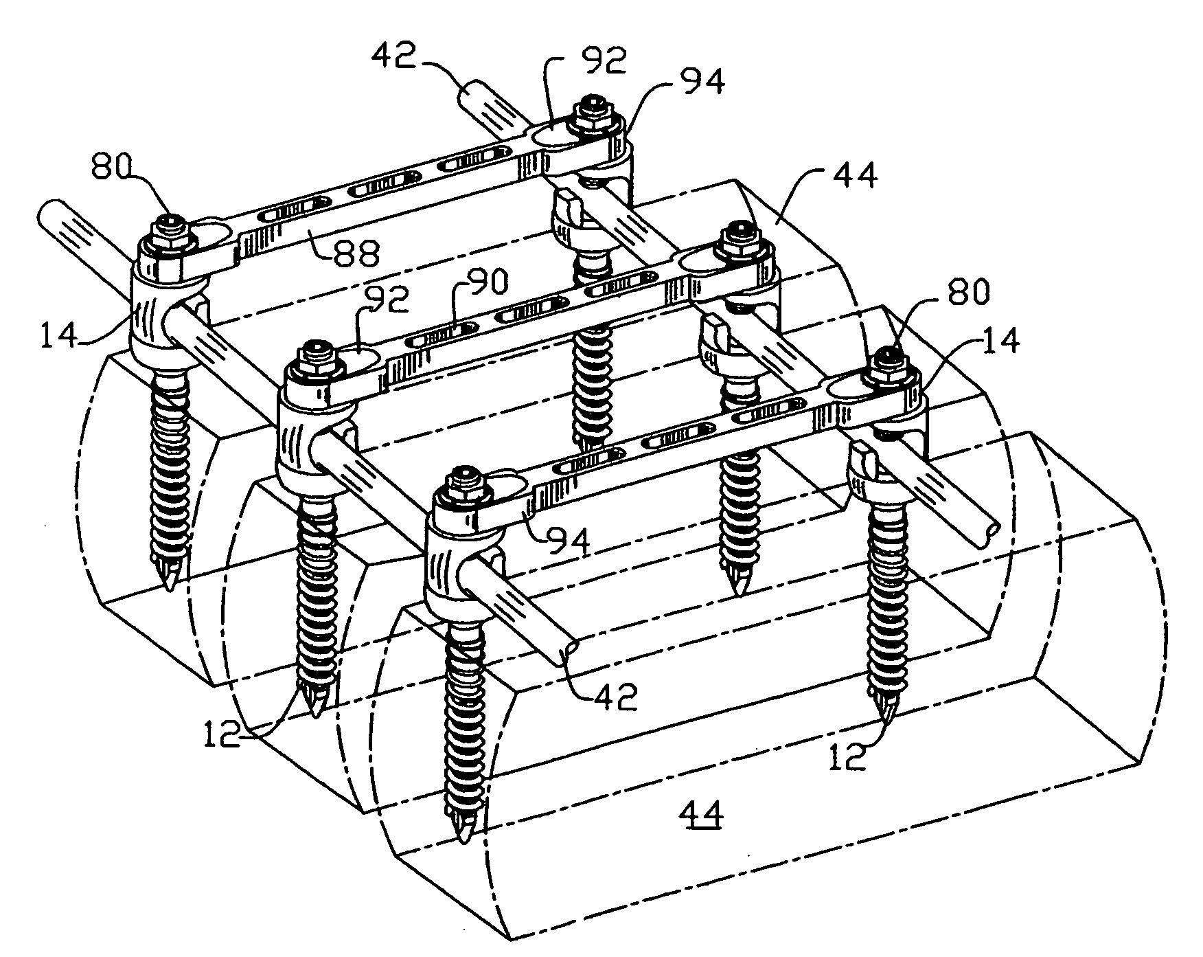
"The present invention provides an apparatus and method for aligning and stabilizing the spinal column. The apparatus includes a screw and a screw cap with a hook for holding a rod, which can be angled relative to the screw. An extension with notches can also be used to hold a rod. The method involves driving bone screws into spinal vertebrae, attaching an extension to each screw with a rod, and securing the rod to the screw cap or under the hook of the screw cap. The technical effects of this invention include improved spinal column alignment and stability."

Problems solved by technology

A problem that arises during surgery utilizing such systems involves the point at which the screw is attached to the rod.
For this reason, it can be difficult for the surgeon to attach the heads of the screws to the rod, particularly when the patient suffers from spinal deformity.
Similarly, in large part because of the difficult geometry caused by the different angles and heights of the pedicular screws, the transfer of the load that is normally carried by the spinal column to the stabilizer through the connection between the rod and the screw is problematical.
However, this prior art device does not appear to lock to the traverse or longitudinal bar to which it is hooked, nor does it include structure that facilitates attachment of the hook to the rod when pedicular screws do not line up and / or are at different heights.

Method used


Image

  • Apparatus ans method for aligning and/or stabilizing the spine
  • Apparatus ans method for aligning and/or stabilizing the spine
  • Apparatus ans method for aligning and/or stabilizing the spine

Examples


Embodiment Construction

)

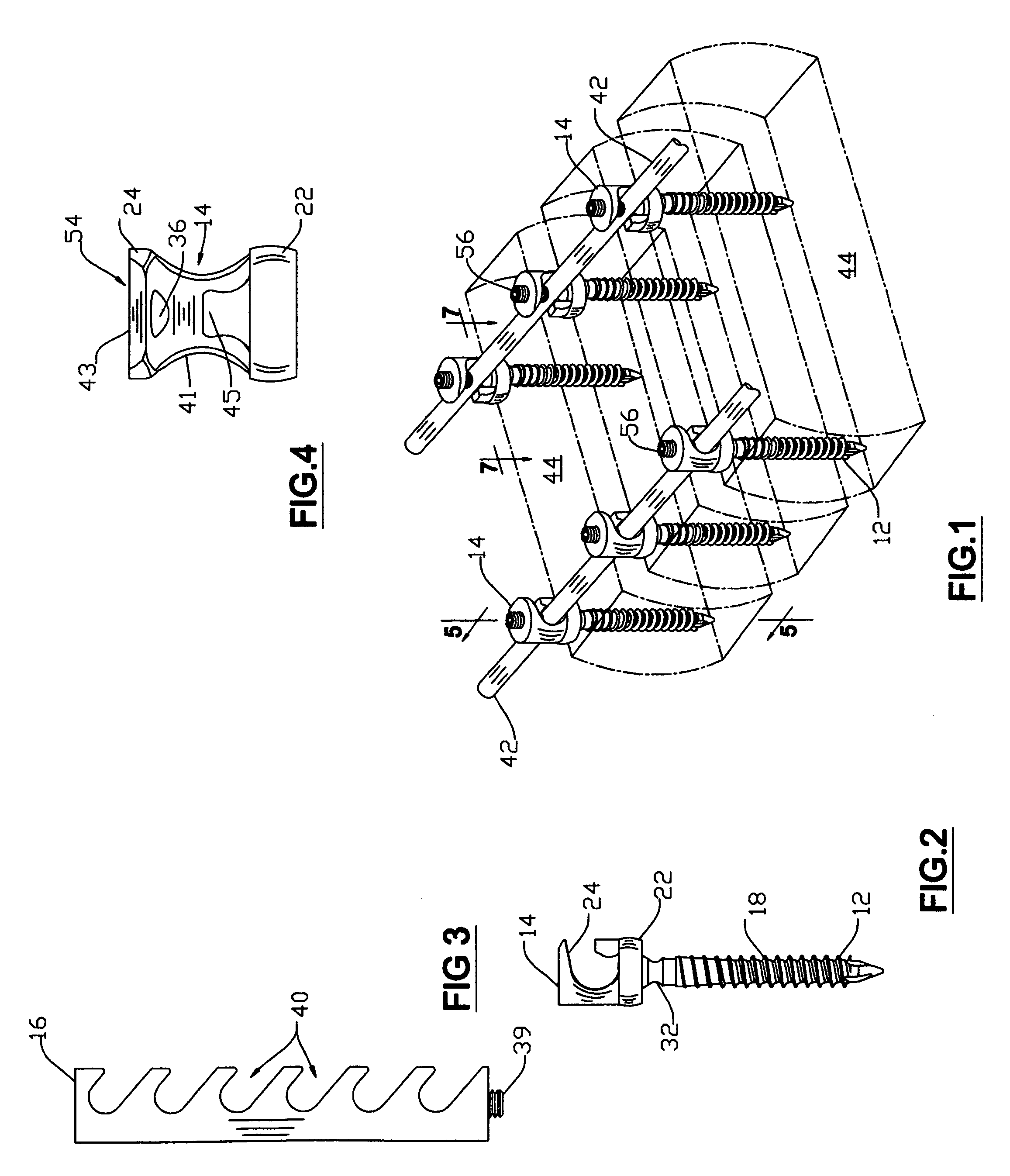
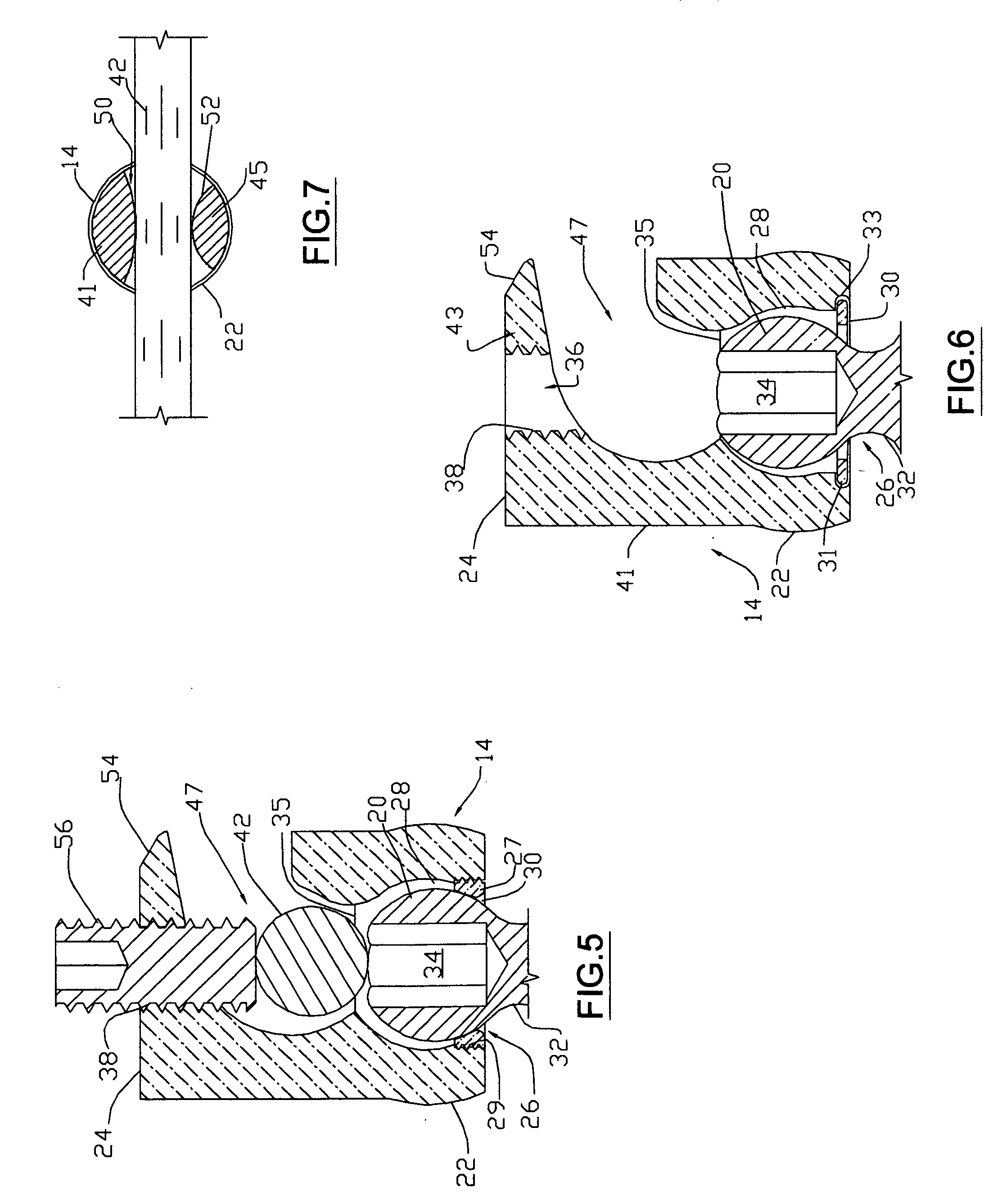
[0033]In more detail, FIGS. 1-5 show a first embodiment of an apparatus for use in aligning and / or stabilizing the spinal column constructed in accordance with the present invention. Apparatus 10 is comprised of screw 12, screw cap 14, and extension 16, screw 12 being of a type known in the art that is comprised of an elongate threaded shank 18 and head 20. Screw cap 14 is comprised of a base 22 having a hook 24 extending therefrom, with means 26 formed in base 22 for retaining screw cap 14 to the head 20 of screw 12.

[0034]As shown in FIG. 5, screw cap retaining means 26 takes the form of a cavity 28 formed in the base 22 of screw cap 14, the cavity 28 being sized so as to receive the rounded head 20 of screw 12 therein while allowing the screw cap 14 to be positioned in an unlimited number of positions relative to screw 12 such that the cavity 28 and the head 20 of screw 12 function in a manner similar to a ball and socket joint. The ability to position screw cap 14 at an unlimite...


PUM


Abstract

Apparatus for use in stabilizing and / or aligning the spinal column. The apparatus utilizes hooks and rods to effectively transfer load from the vertebrae to the apparatus regardless of the angle and the height of the pedicular screws. The screws are retained to a screw cap that includes a hook forming a cradle for receiving the rod therein and a bore to which an extension is releasably secured. The extension includes a plurality of notches forming a ladder, each notch being formed so as to releasably retain the rod to the notch so that the rod can be moved down the ladder until it is positioned in the cradle of the screw cap, after which the extension is removed from the screw cap and a set screw is utilized to secure the rod in the cradle. The apparatus is also configured for transverse spinal fixation with rods that extend across the vertebral body to which longitudinal rods are affixed.

Description

BACKGROUND OF THE INVENTION[0001]The present invention relates to an apparatus for aligning and / or stabilizing the spinal vertebrae. More specifically, the present invention relates to “hook and rod” external spinal stabilizers and / or alignment systems that facilitate alignment of the vertebrae using such stabilizers and / or systems.[0002]Stabilization and / or alignment of the spinal column is indicated for treatment of many pathologies including trauma, tumor, infection, degenerative spine disease, iatrogenic spinal instability, spondylolysis / spondylolisthesis, pseudarthrosis, kyphosis, and spinal deformity. A number of stabilizers for treating such pathologies are disclosed in the scientific and patent literature, and are available commercially from such vendors as Sofamor-Danek, Osteonics, and others, that utilize so-called “hook and rod” components. Such stabilizers utilize screws that are driven into the bodies of adjacent vertebrae, typically in the pedicular region of the verte...

Claims


Application Information

Patent Timeline
Patent Type & Authority Applications(United States)
IPC IPC(8): A61B17/70A61B17/04
CPCA61B17/7007A61B17/7034A61B17/7049A61B17/7043A61B17/7037
Inventor PISHARODI, MADHAVAN
Owner PERUMALA CORP
Learn More