Electric actuator
a technology of electric actuators and actuators, which is applied in the direction of gearing details, mechanical equipment, gearing, etc., can solve the problems of adverse effects on the productivity (ease in manufacturing) affecting the productivity of the electric actuators b>1/b> including the feed screw shaft b>6/b>, and lowering the productivity of the electric actuators. , to achieve the effect of enhancing the productivity of the electric actuator,
- Summary
- Abstract
- Description
- Claims
- Application Information
AI Technical Summary
Benefits of technology
Problems solved by technology
Method used
Image

Examples
first embodiment
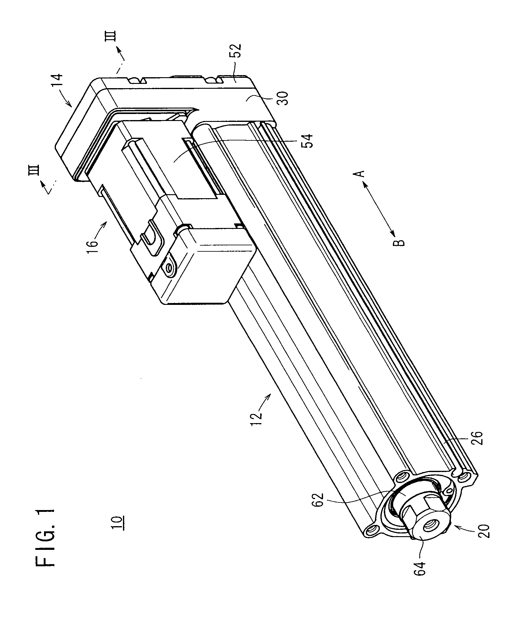
[0030]In FIG. 1, reference numeral 10 designates an electric actuator according to the present invention.
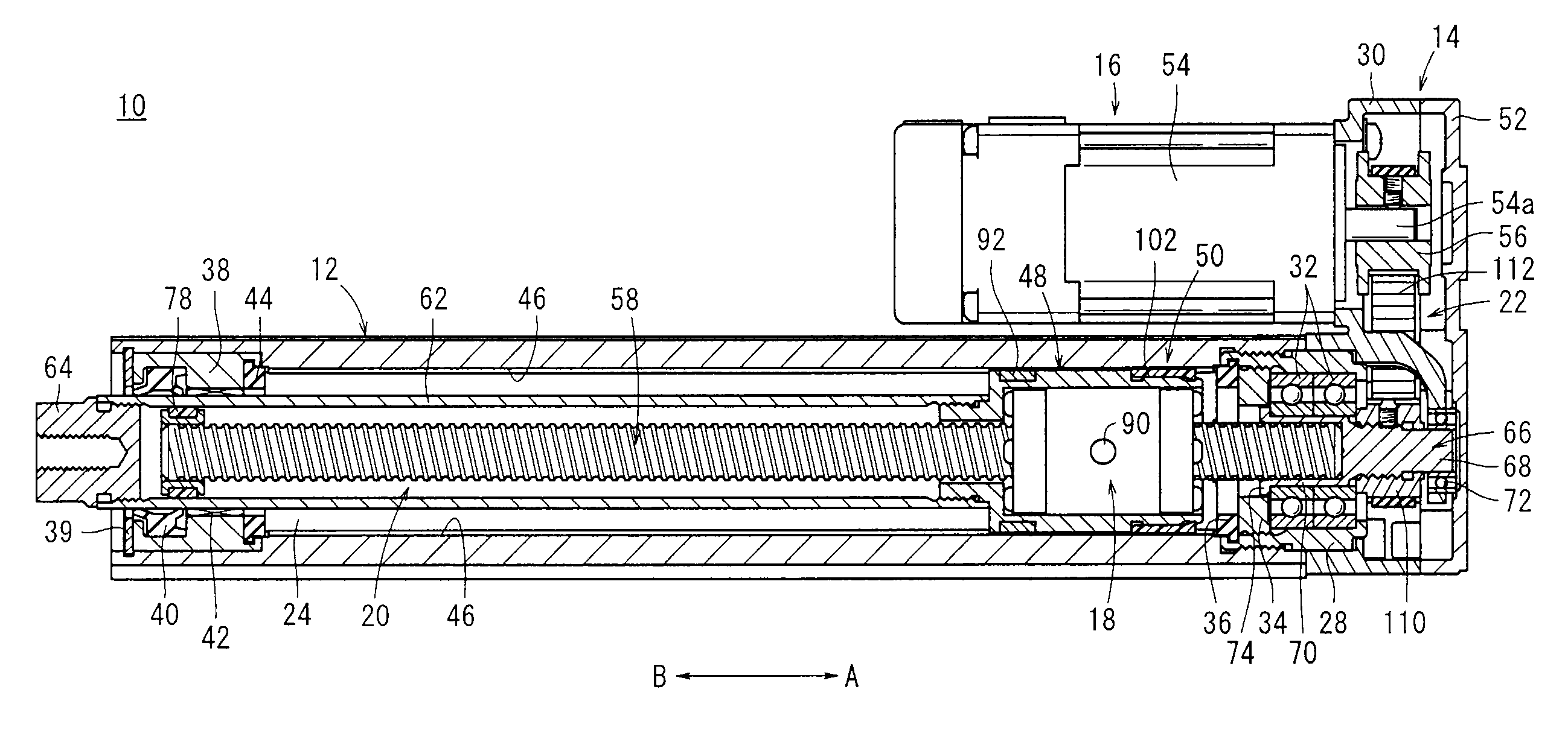
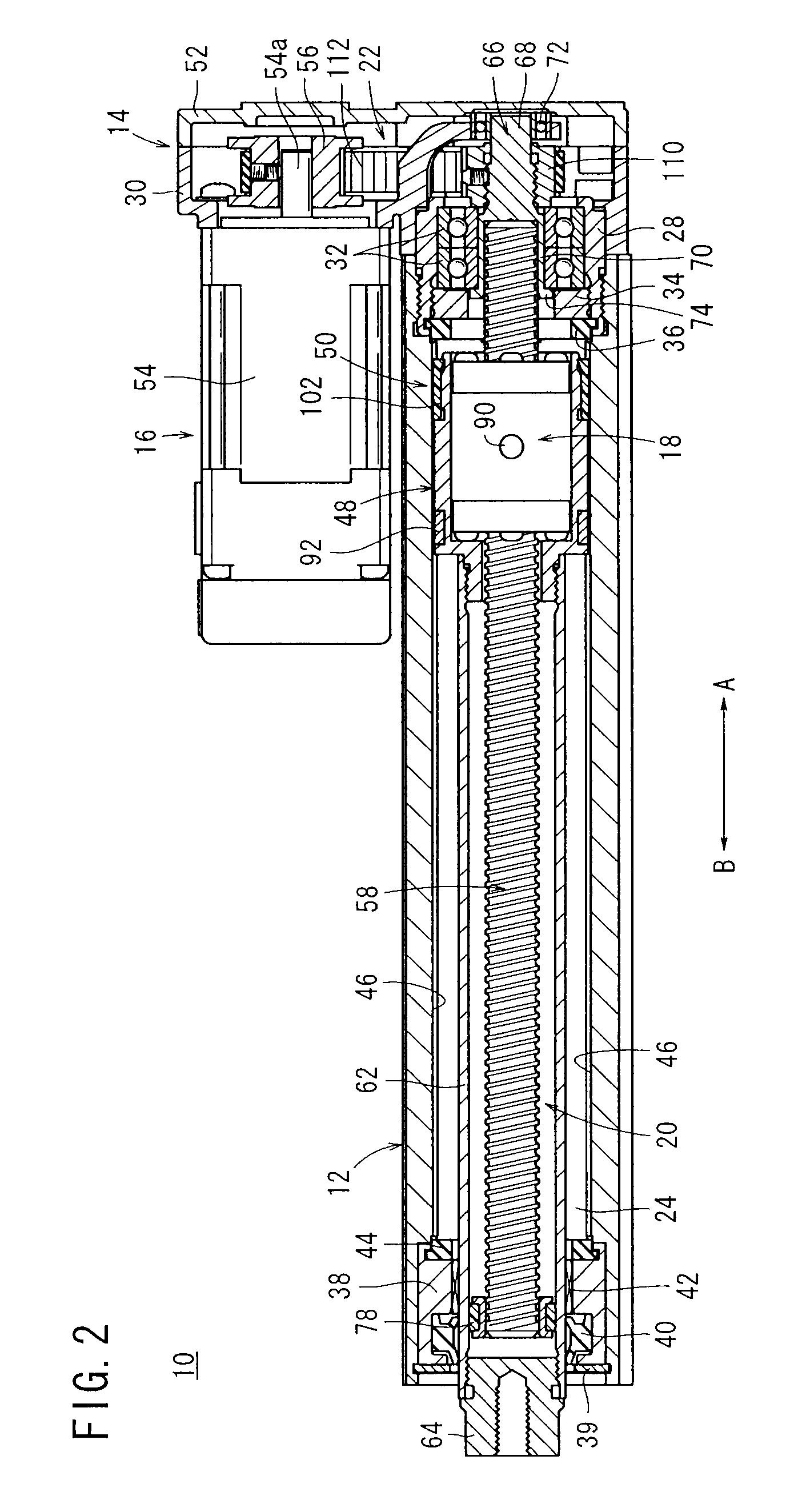
[0031]As shown in FIGS. 1 to 3, the electric actuator 10 comprises an elongate body 12 extending along the axial direction (the direction of arrows A and B), a cover unit 14 coupled to one end of the body 12, a driving section 16 disposed substantially parallel to the body 12 and which is rotatably driven by an electric signal supplied thereto, a displacement mechanism 20 disposed in the interior of the body 12 and having a displacement nut 18, which is capable of being displaced over a given stroke by a drive force from the driving section 16, and a drive force transmission mechanism 22 that transmits the drive force from the driving section 16 to the displacement mechanism 20.
[0032]A hole 24 that opens with a circular shape in cross section penetrates along the axial direction (the direction of arrows A and B) of the body 12, and on the outer circumferential surface of the body...
second embodiment
[0096]In this manner, by providing the variable speed unit 152 in the electric actuator 150 after the rotary drive force from the driving section 16 has been suitably changed in speed through the planetary gear mechanism 154 that constitutes the variable speed unit 152, the rotary drive force is transmitted to the displacement mechanism 20, whereby the piston 48 and the piston rod 62 can be displaced at a desired velocity and displacement amount.
PUM
 Abstract
Description
Claims
Application Information
 - Generate Ideas
- Intellectual Property
- Life Sciences
- Materials
- Tech Scout
- Unparalleled Data Quality
- Higher Quality Content
- 60% Fewer Hallucinations
Browse by: Latest US Patents, China's latest patents, Technical Efficacy Thesaurus, Application Domain, Technology Topic, Popular Technical Reports.
© 2025 PatSnap. All rights reserved.Legal|Privacy policy|Modern Slavery Act Transparency Statement|Sitemap|About US| Contact US: help@patsnap.com