Hair styling apparatus with retractable styling heads

Inactive Publication Date: 2009-10-22
DICKSON IND CO LTD
View PDF17 Cites 24 Cited by
  • Summary
  • Abstract
  • Description
  • Claims
  • Application Information

AI Technical Summary

Benefits of technology

[0026]Preferably, said styling member comprises an electric heating means, and power is supplied to said heating means only when said styling member has been extended for a predetermined length from s

Problems solved by technology

Although tong-type hair styling apparatus and rod-type hair styling apparatus provide a useful

Method used


Image

  • Hair styling apparatus with retractable styling heads
  • Hair styling apparatus with retractable styling heads
  • Hair styling apparatus with retractable styling heads

Examples


Embodiment Construction

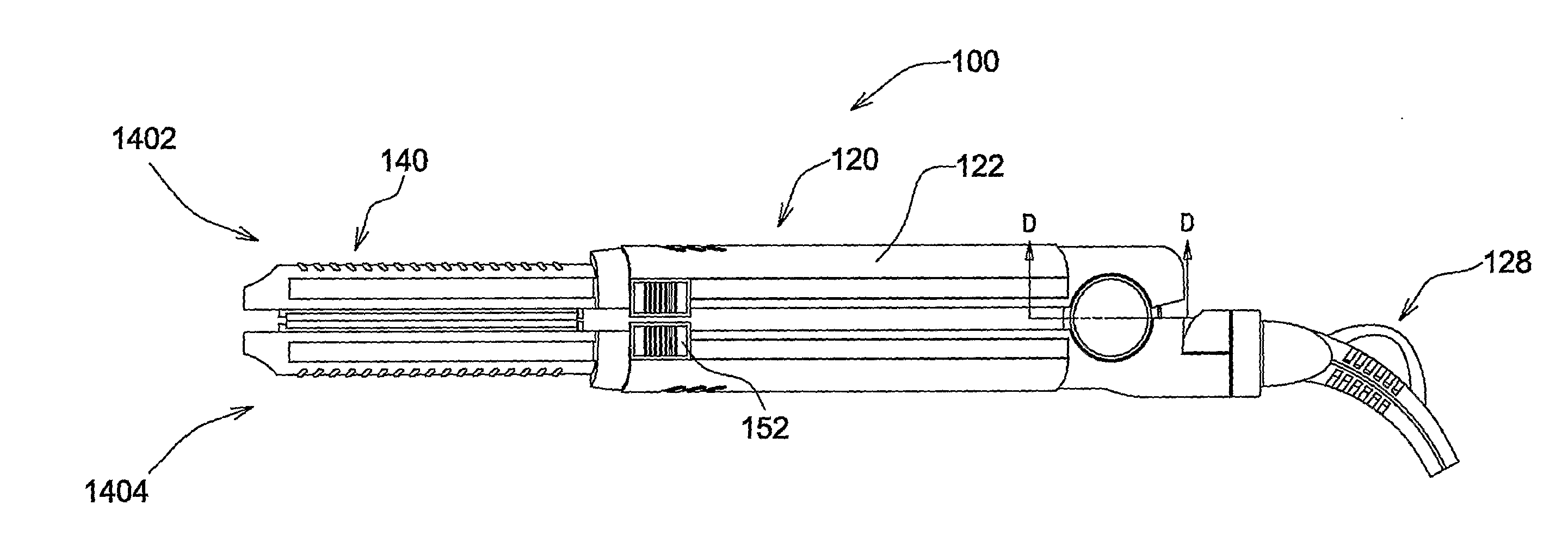
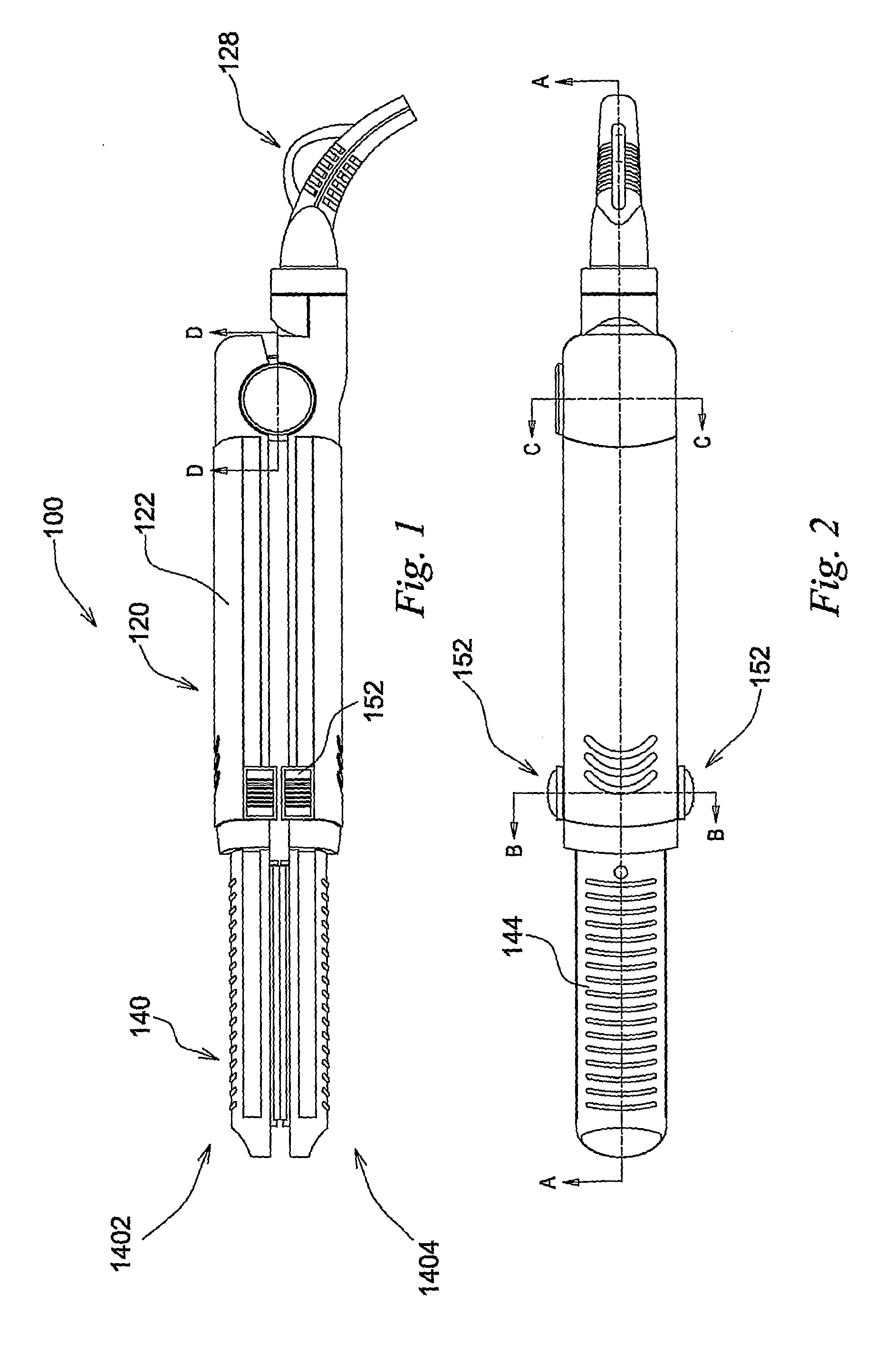
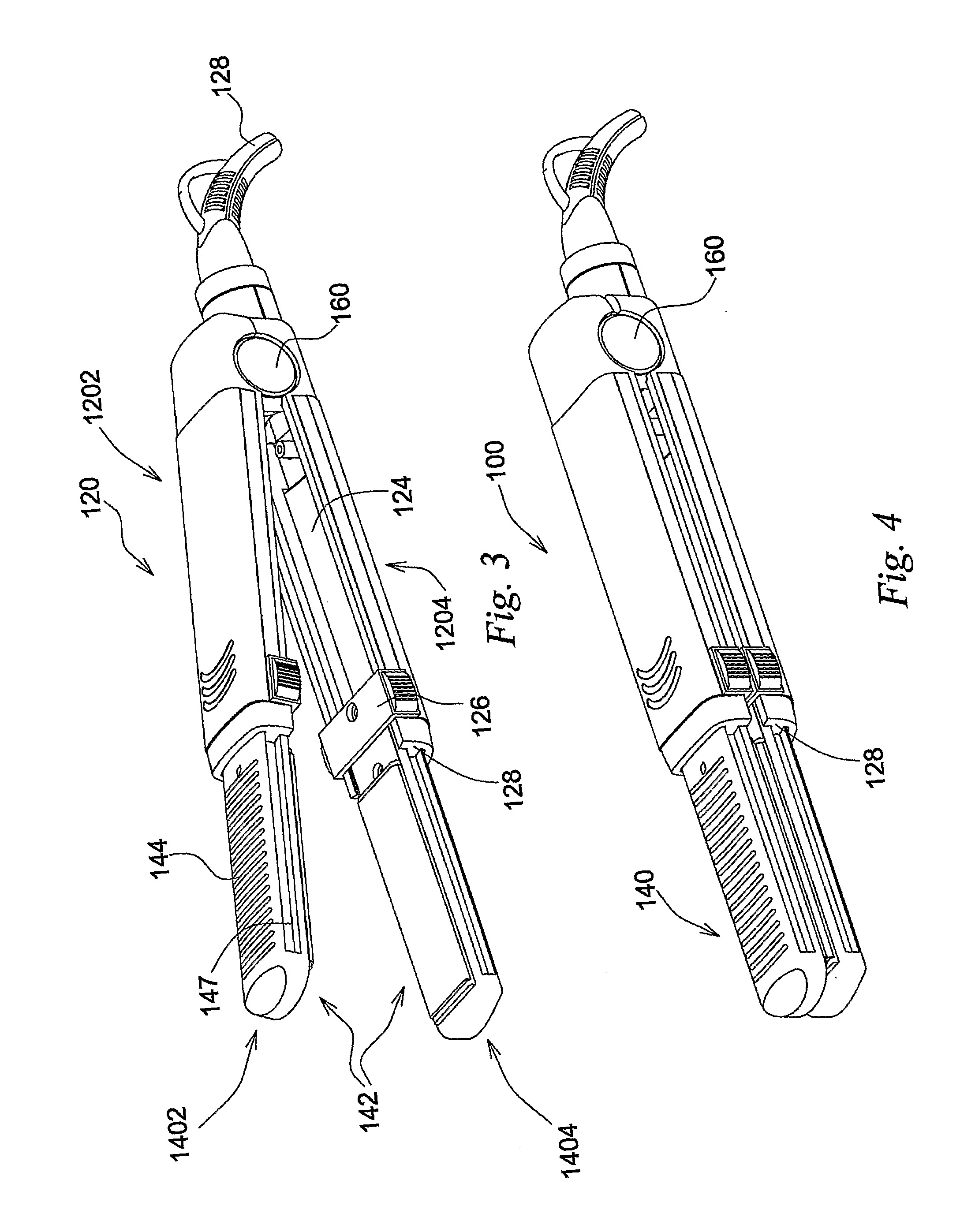
[0038]Referring to the Figures, there is shown a hair straightener 100 as an example of a preferred embodiment of this invention. The hair straightener 100 comprises a handle 120, a styling head 140 and an electric heating means.

[0039]The handle 120 comprises a pair of arms 1202, 1204 which is pivotally joined at their respective distal ends. Each of the pivotally joined arms comprises a hollow housing 122 which defines a hollow receptacle for receiving a styling member of the styling head to be explained below. The hollow arm housing 122 is preferably made of durable plastics or other insulated materials in order to provide good thermal and electrical insulation. The hollow receptacle is elongate and extends along an axial direction which is orthogonal to the pivotal axis of the pivotal joint interconnecting the pair of arms 1202, 1204. A coil spring 154 is mounted at the pivotal joint to provide spring bias for urging the pair of arms towards an opened configuration. The handle is...


PUM


Abstract

A hair styling apparatus includes a handle, a styling head and a heater. The handle has a pair of pivotally joined arms, and the head includes a pair of styling members which cooperate to form styling surfaces of the styling head. Each styling member is extendable from and retractable into the handle.

Description

FIELD OF THE INVENTION[0001]This invention relates to hair styling apparatus and, more particularly, to hand-held hair styling apparatus with a retractable styling head. More specifically, this invention relates to tong-type hair styling apparatus with a retractable hair styling head.BACKGROUND OF THE INVENTION[0002]Hair styling apparatus are widely used for hair styling applications, for example, hair curling and hair straightening. A typical hair styling apparatus comprises a handle and a heated styling head for contact or non-contact styling. A common contact-type hair styling apparatus resembles the shape of a pair of tongs and comprises a pair of hinged arms with a pair of heated styling heads. The styling heads protrude from the free ends of the hinged arms with hair styling surfaces facing each other. Typically, hair is styled when hair is held between a pair of heated styling heads and when they are in compressive engagement. Styling is done, for example, by a pair of heated...

Claims


Application Information

Patent Timeline
IPC IPC(8): A45D1/00
CPCA45D1/04A45D2/001A45D1/08A45D1/06
Inventor CHAN, WING KIN
Owner DICKSON IND CO LTD
Why Eureka
Try Eureka