
Method of detecting a useful signal

a useful signal and signal detection technology, applied in the direction of amplitude demodulation, motor/generator/converter stopper, interference reduction, etc., can solve the problem of filter algorithm display, control or regulation of parameters based on analysis no longer being adequately possible, and complicating or distorting analysis of parameters. problem, to achieve the effect of reducing the computational complexity of detecting

Inactive Publication Date: 2009-10-22
ZF FRIEDRICHSHAFEN AG
View PDF11 Cites 1 Cited by
  • Summary
  • Abstract
  • Description
  • Claims
  • Application Information

AI Technical Summary

Benefits of technology

[0012]The invention is therefore based on the task of devising a method of the type discussed here that minimizes the computational complexity of detecting a useful signal from a measurement signal that is overlaid by at least one interference signal, so that the useful signal can be detected in real time by the control or regulating device, for example in a motor vehicle.
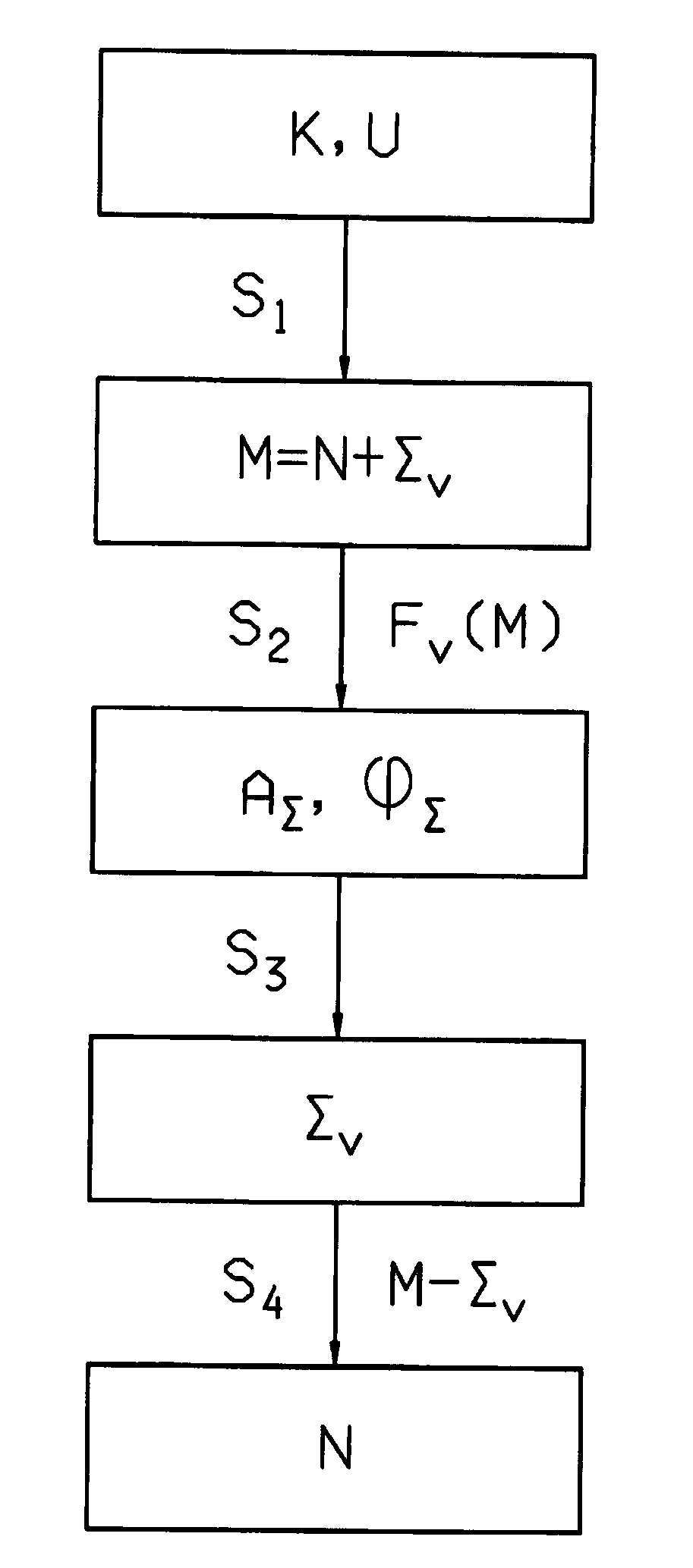
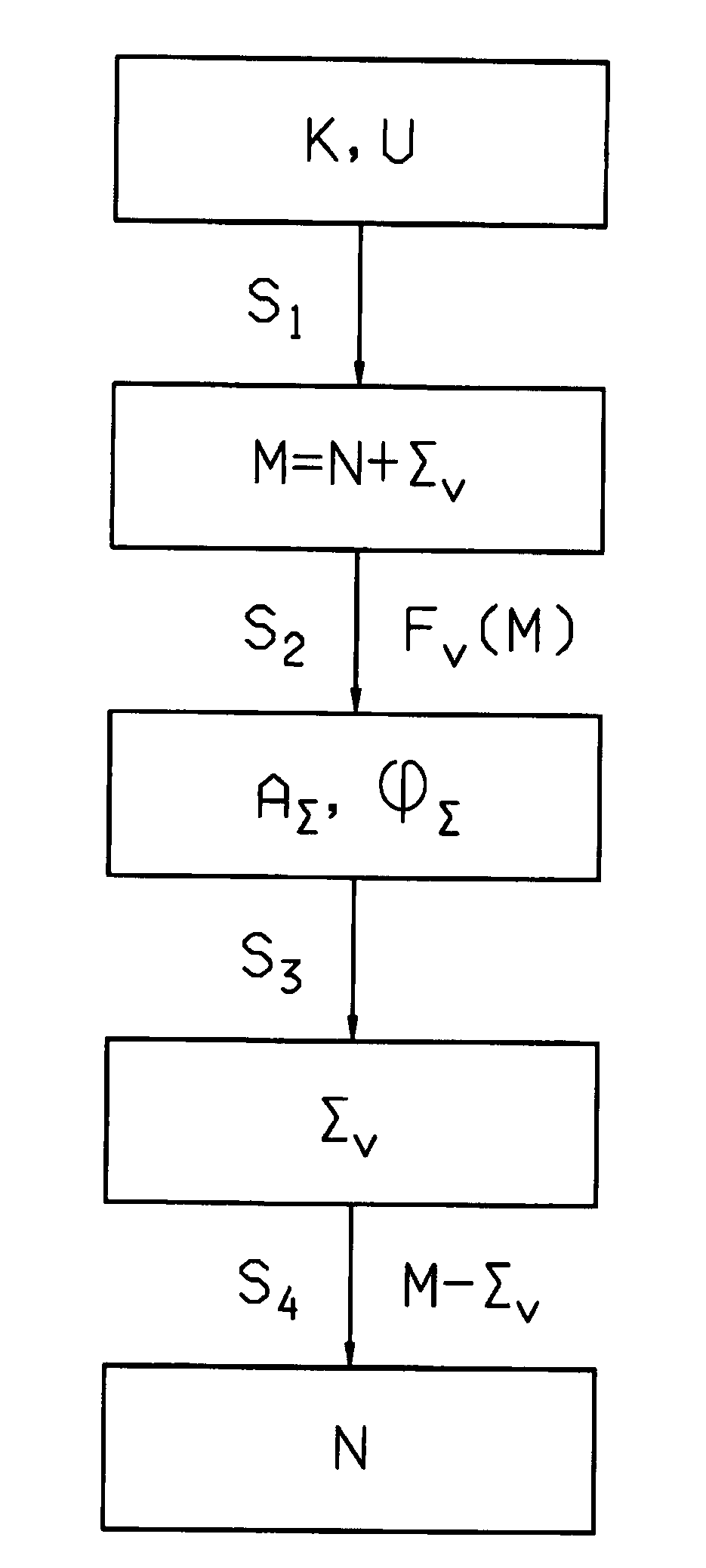
[0014]The essence of the invention consists of the Fourier transformation performed during the second step not being performed with reference to a plurality of frequencies, as in the state of the art, but rather only with reference to the known interference signal frequency. That results in a major reduction in the computational complexity of detecting the useful signal from the measurement signal, so that the useful signal can be detected in real time by the control or regulating device of a motor vehicle.
[0016]In a first constructional variant of the method of the invention, detection of the measuring signal is done during a first step on the basis of the actuating position of a clutch of the motor vehicle when the cause of the interference signal is a wobbling of the drive shaft of the motor vehicle drive motor. Wobbling occurs when unbalances occur on the shaft of the drive motor. These unbalances can be inherent and / or caused by wear due to operation. The longer a motor vehicle is in operation, the more wear and thus unbalance increase, which leads to greater wobbling and the corresponding interference signals. The method of the invention is therefore particularly advantageous for motor vehicles that have been in use for an extended period.

Problems solved by technology

The interference signals in the measurement signals quite often reach a magnitude that complicates or distorts analysis of the parameter to such an extent that the control or regulation of the parameter based on the analysis is no longer adequately possible.
However, these filter algorithms display numerous disadvantages.
Thus, depending on the filter frequency or the cut-off frequency used at any given time, a phase delay can occur, which can have an adverse effect on a parameter.
This is often adjusted for by using of a plurality of filters with different filter frequencies, but this is very complicated in terms of construction.
If characteristic curves with steep gradients are required for the filters, the filter order also increases, and therefore the number of filter parameters, which also increases software and / or construction complexity.
Wavelet transformations are very complicated in computational terms and cannot normally be used to control or regulate parameters in real time due to the limited computing power of the control or regulating devices of motor vehicles.
The disadvantage of Fourier transformations is that they are usually done with reference to a plurality of frequencies.
Here too, the computational complexity is often so great that no analysis of the measurement signal in real time, and therefore also no control or regulation of the parameters on which the measurement signal is based, can be done by the control or regulating device of motor vehicles.

Method used


Image

  • Method of detecting a useful signal
  • Method of detecting a useful signal

Examples


Embodiment Construction

[0023]As shown in FIG. 1, the starting point of the method of the invention is a parameter K specific to the operation of a motor vehicle component and a cause U of an interference with a known cycle. In motor vehicles, certain combinations of the parameter K and the cause U are especially typical. Examples of combinations of this type are the actuating position of the starting clutch of the motor vehicle as parameter K and a wobbling of the drive shaft of the motor vehicle drive motor as cause U of the interference, the actuating position of the starting clutch of the moor vehicle as parameter K and a judder vibration of the clutch as cause U of the interference, the mean initial rotational speech of the transmission of the motor vehicle as parameter K and a natural oscillation of the drive train as cause U of the interference, or the rotational speed of the wheels of the motor vehicle as parameter K and a natural vibration of the drive train as cause U. Other combinations commonly...


PUM


Abstract

A method of detecting a useful signal from a measurement signal that is overlaid by at least one interference signal for use in a control or regulating device, where the interference signal occurs with at least one known interference signal frequency. The method including the steps of detecting the measurement signal, performing a Fourier transformation on the measurement signal with reference to the interference signal frequency to detect the interference signal amplitude and phase, detecting the interference signal on the basis of the interference signal amplitude and phase, and removing the interference signal from the measurement signal to detect the useful signal. The Fourier transformation is performed only with reference to the known interference signal frequency to simplify the computation making it possible to detect the useful signal in real time.

Description

[0001]This application claims priority from German patent application serial no. 10 2008 001 202.5 filed Apr. 16, 2008.FIELD OF THE INVENTION[0002]The invention relates to a method for detecting a useful signal from a measurement signal that is overlaid by at least one interference signal in, for example, a control or regulating device of a motor vehicle or the like, when the interference signal occurs with at least one known interference signal frequency.BACKGROUND OF THE INVENTION[0003]A measurement signal for detecting the parameters of technical devices is the preferred means in many areas of technology for analyzing parameters and controlling or regulating these parameters on the basis of this analysis. The measurement signals usually exist in electronic form, such as electric voltages, for example.[0004]Motor vehicle technology is one area of technology in which measurement signals play an important role is. They are used there to detect the parameters of various components of...

Claims


Application Information

Patent Timeline
Patent Type & Authority Applications(United States)
IPC IPC(8): H02P6/16H04B1/10
CPCG01R31/007G01R19/2506
Inventor BITZER, FRANZ
Owner ZF FRIEDRICHSHAFEN AG
Learn More