
System and methods for network image delivery with dynamic viewing frustum optimized for limited bandwidth communication channels

a network image and dynamic viewing technology, applied in the field of network image distribution systems, can solve the problems of inherently increasing latency in resolving finer levels of detail, insufficient bandwidth for network image delivery, etc., to achieve the effect of reducing the computational complexity of determining request prioritization, reducing the computational complexity of determining request priority, and reducing the computational complexity of determining client processing power

Active Publication Date: 2006-11-21
BRADIUM TECHOLOGIES LLC
View PDF7 Cites 20 Cited by
  • Summary
  • Abstract
  • Description
  • Claims
  • Application Information

AI Technical Summary

Benefits of technology

"The present invention provides an efficient system and methods for optimally presenting image data on client systems with limited processing performance, resources, and communications bandwidth. The system includes a parcel request subsystem and a parcel rendering subsystem. The parcel request subsystem requests image data in priority order and stores it in a data store. The parcel rendering subsystem selectively retrieves and renders the image data to a display. The prioritization of image data requests is based on the display resolution of the client system. The system requires minimal client processing power and storage capacity and can be easily downloaded to conventional computer systems or embedded in dedicated function devices. It can also be used with low to very low bandwidth network connections. The image parcel data is compressed to obtain fixed size transmission data blocks, which enables the data to be delivered to the client in bounded time frames. The system also allows for multiple data forms to be transferred to the client for concurrent display."

Problems solved by technology

As well recognized problem with such conventional systems is that full resolution image presentation is subject to the inherent transfer latency of the network.
The inverse-transform function performed by the client computer is, however, highly compute intensive.
Consequently, there is an inherently increasing latency in resolving finer levels of detail.
Significant problems remain in permitting the convenient and effective use of complex images by many different types of client systems, even with the improvements provided by the various conventional systems.
In particular, the implementation of conventional image visualization systems is generally unworkable for smaller, often dedicated or embedded, clients where use of image visualization would clearly be beneficial.
Small clients, however, typically have restricted performance processors with no dedicated floating-point support, little general purpose memory, and extremely limited persistent storage capabilities, particularly relative to common image sizes.
Such systems are not readily capable, if at all, of performing complex, compute-intensive Fourier or wavelet transforms, particularly within a highly restricted memory address space.
That is, resolution resolved image data provided to the client is unconstrained by any limitation in the client system to actually display the corresponding image.
Another problem is that small clients are generally constrained to generally to very limited network bandwidths, particularly when operating under wireless conditions.
Such limited bandwidth conditions may exist due to either the direct technological constraints dictated by the use of a low bandwidth data channel or indirect constraints imposed on relatively high-bandwidth channels by high concurrent user loads.
Reliable transport protocols, however, merely mask packet losses and the resultant, sometimes extended, recovery latencies.
When such covered errors occur, however, the aggregate bandwidth of the connection is reduced and the client system can stall waiting for further image data to process.

Method used


Image

  • System and methods for network image delivery with dynamic viewing frustum optimized for limited bandwidth communication channels
  • System and methods for network image delivery with dynamic viewing frustum optimized for limited bandwidth communication channels
  • System and methods for network image delivery with dynamic viewing frustum optimized for limited bandwidth communication channels

Examples


Embodiment Construction

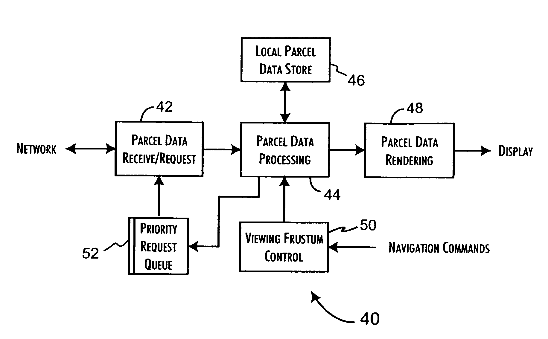
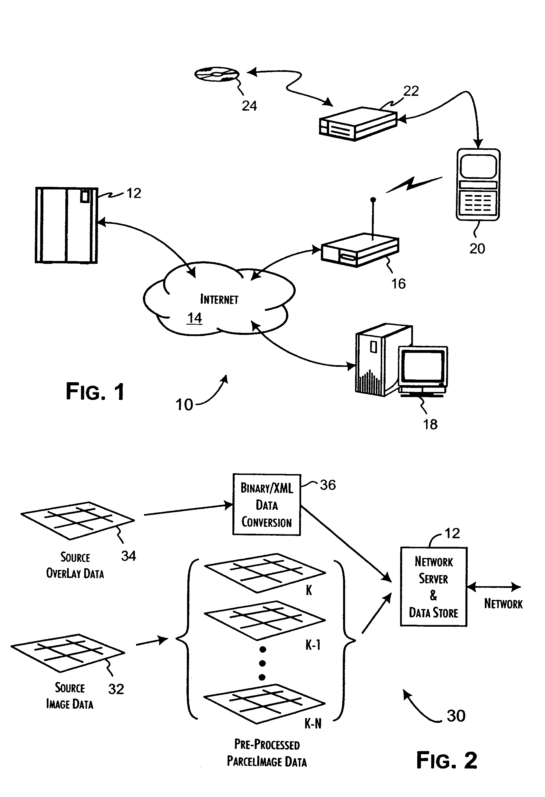
[0035]The preferred operational environment 10 of the present invention is generally shown in FIG. 1. A network server system 12, operating as a data store and server of image data, is responsive to requests received through a communications network, such as the Internet 14 generally and various tiers of internet service providers (ISPs)z including a wireless connectivity provider 16. Client systems, including conventional workstations and personal computers 18 and smaller, typically dedicated function devices often linked through wireless network connections, such as PDAs, webphones 20, and automobile navigation systems, source image requests to the network server 12, provide a client display and enable image navigational input by a user of the client system. Alternately, a dedicated function client system 20 may be connected through a separate or plug-in local network server 22, preferably implementing a small, embedded Web server, to a fixed or removable storage local image repos...


PUM


Abstract

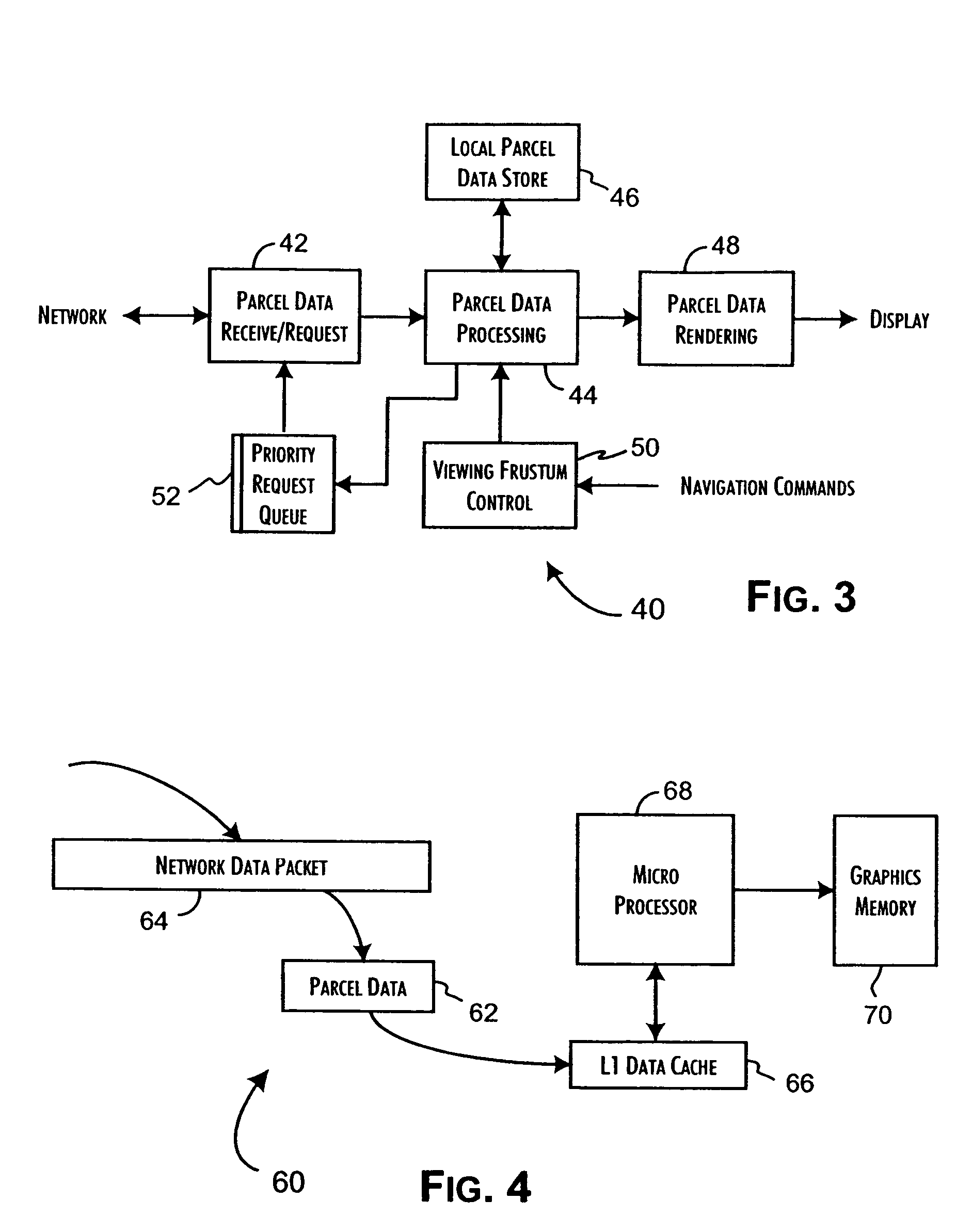
Dynamic visualization of image data provided through a network communications channel is performed by a client system including a parcel request subsystem and a parcel rendering subsystem. The parcel request subsystem includes a parcel request queue and is operative to request discrete image data parcels in a priority order and to store received image data parcels in a parcel data store. The parcel request subsystem is responsive to an image parcel request of assigned priority to place the image parcel request in the parcel request queue ordered in correspondence with the assigned priority. The parcel rendering subsystem is coupled to the parcel data store to selectively retrieve and render received image data parcels to a display memory. The parcel rendering system provides the parcel request subsystem with the image parcel request of the assigned priority.

Description

[0001]This application claims the benefit of U.S. Provisional Application Nos. 60 / 258,488, 60 / 258,485, 60 / 258,465, 60 / 258,468, 60 / 258,466, and 60 / 258,467, all filed Dec. 27, 2000.CROSS-REFERENCE TO RELATED APPLICATIONS[0002]The present application is related to the co-pending application Optimized Image Delivery over Limited Bandwidth Communication Channels, Levanon et al., filed concurrently herewith and which is assigned to the Assignee of the present Application.BACKGROUND OF THE INVENTION[0003]1. Field of the Invention[0004]The present invention is related to network based, image distribution systems and, in particular, to a system and methods for efficiently selecting and distributing image parcels through a narrowband or otherwise limited bandwidth communications channel to support presentation of high-resolution images subject to dynamic viewing frustums.[0005]2. Description of the Related Art[0006]The Internet and other network systems provide a unique opportunity to transmi...

Claims


Application Information

Patent Timeline
Patent Type & Authority Patents(United States)
IPC IPC(8): G06F15/16G06F3/153G06F3/14G06T3/40G06T17/20
CPCG06F3/14G06T3/403G06T3/4092G06T17/20G09G2340/02G06F13/00
Inventor LEVANON, ISAACLAVI, YONI
Owner BRADIUM TECHOLOGIES LLC
Learn More