Method of estimating a velocity magnitude of a moving target in a horizontal plane and radar detection system

a horizontal plane and velocity magnitude technology, applied in the field of radar detection, can solve the problems of degrading affecting the accuracy of estimation, and not always accurate estimation of target velocity, so as to improve the accuracy of method estimation, reduce computational complexity, and improve the effect of calculation results

Active Publication Date: 2019-11-28
APTIV TECH LTD
View PDF0 Cites 13 Cited by
  • Summary
  • Abstract
  • Description
  • Claims
  • Application Information

AI Technical Summary

Benefits of technology

[0027]This is a particularly advantageous way of incorporating the estimated orientation uncertainty into the method of estimating the velocity magnitude and thereby using even less computational complexity.
[0028]It is preferred if a variance esti

Problems solved by technology

However, this indication, which may be denoted as compensated range rate, is usually not an accurate estimate of the velocity of the target due to degrading influence factors such as noise.
Furthermore, the range rates of neighbouring points of reflection of a given cluster can vary, thus leading to uncertainty of estimating the velocity from the points of reflection.
In particular, so called wheel-spin detections (i.e., the velocity measured from the wheel speed of the host vehicle does not match with the true speed of the vehicle due to wheel slipping) and clutter (i.e., points of reflection which are not located on the target) can degrade the accuracy of the estimation.
Indeed, even when the so-called velocity profile equation is derived from a large number of points of reflection, the estimation can be heavily degraded due to a small number of noisy points of reflection (i.e., outliers).
One problem associated with robust estimation algorithms known from the art and which can be employed for estimating the velocity of a target in the scenario described above is that the quality of the es

Method used


Image

  • Method of estimating a velocity magnitude of a moving target in a horizontal plane and radar detection system
  • Method of estimating a velocity magnitude of a moving target in a horizontal plane and radar detection system
  • Method of estimating a velocity magnitude of a moving target in a horizontal plane and radar detection system

Examples


implementation example

[0154]The proposed algorithm was implemented in a vehicle in order to assess the performance of an object hypotheses algorithm. The proposed object hypotheses algorithm is used for velocity estimation in case of valid orientation estimation and invalid velocity estimation.

[0155]FIG. 10 shows a flow chart indicated the steps of the process flow of the object hypotheses velocity run algorithm that can be implemented in the evaluation unit of the radar detection system 5′. The process starts at box 20 at box 22 a decision is made whether the object hypotheses model is a point model or not.

[0156]If the decision is made that the object hypotheses model is a point model, then a decision is made at box 24 whether the azimuth rate is invalid.

[0157]If this is the case then a velocity status of the nearest detection is verified at box 26. If a decision is made that the velocity status of the nearest detection is verified then a decision is made at box 28 that the range rate is the same as the...


PUM


Abstract

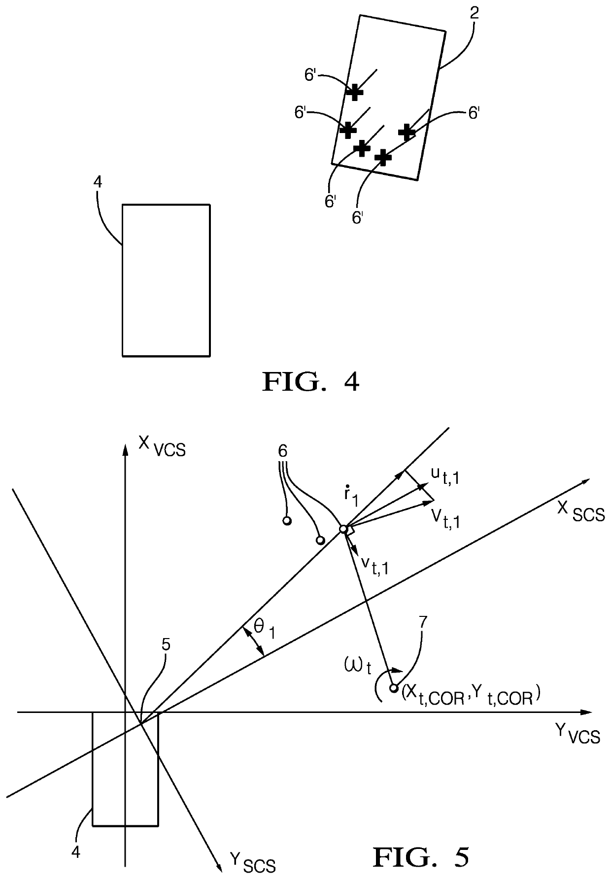
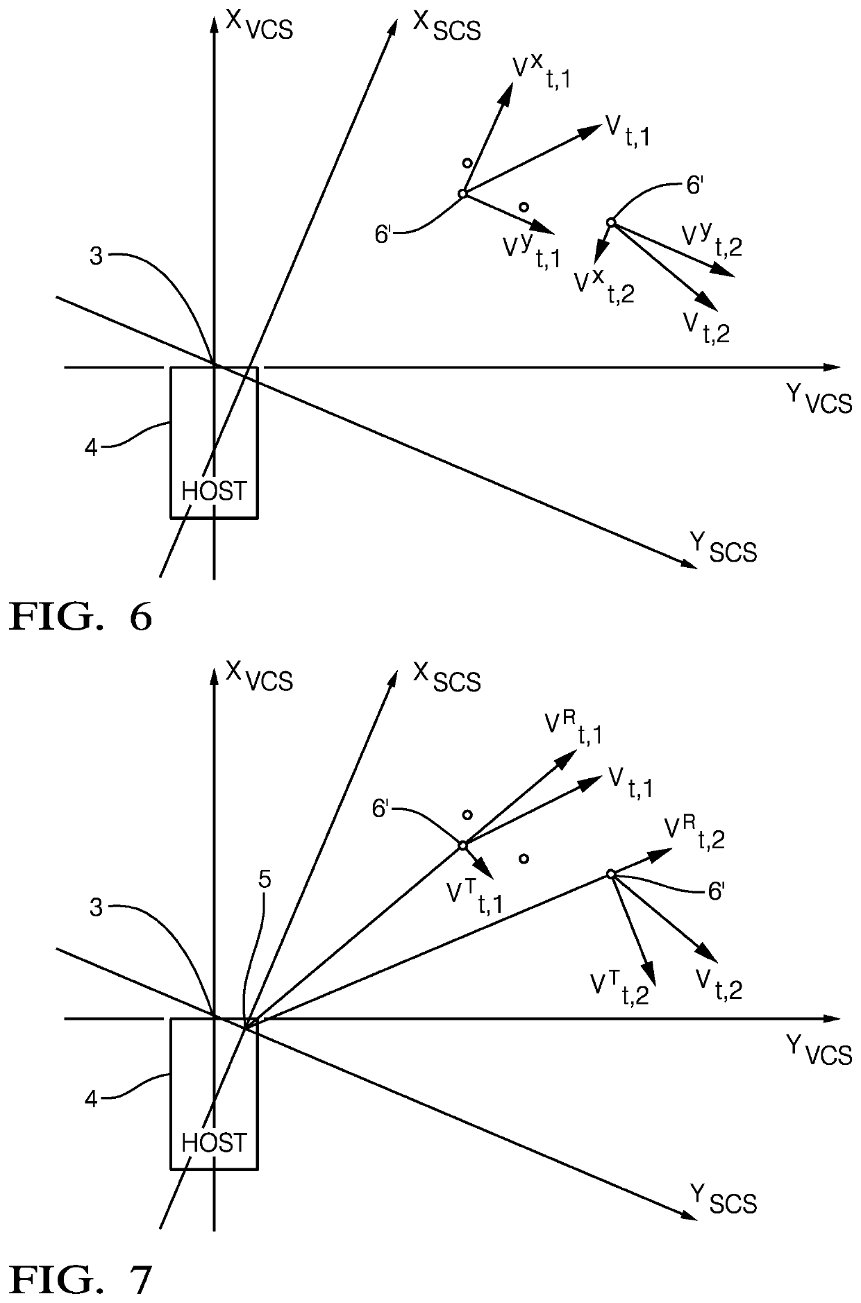
The present invention relates to a method of estimating a velocity magnitude of a moving target in a horizontal plane using radar signals received by a radar detection system, the radar detection system being configured to resolve multiple dominant points of reflection, i.e. to receive a plurality of radar signals from the moving target in a single measurement instance of a single, wherein each of the resolved points of reflection is described by data relating to a range, an azimuth angle and a raw range rate of the points of reflection in said single radar measurement instance. The invention further relates to a radar detection system.

Description

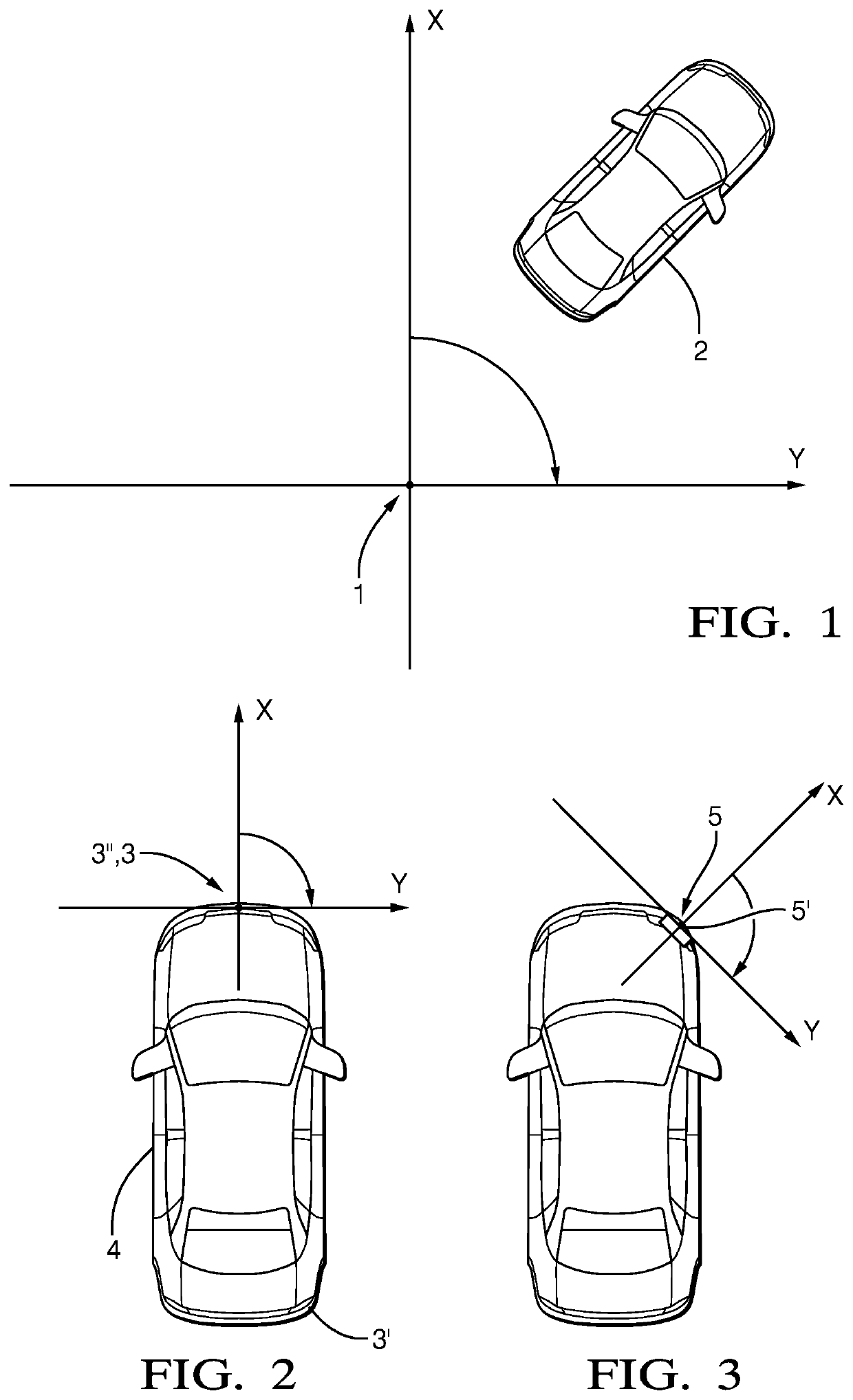
TECHNICAL FIELD OF INVENTION[0001]This disclosure generally relates to radar detection.BACKGROUND OF INVENTION[0002]Vehicles can be equipped with radars systems used to classify the environment in the vicinity of the vehicle such as to, e.g., detect moving or static objects around the vehicle. Such systems are, for example, used to estimate the motion state of other vehicles for automotive perception systems and can be used in active safety, driver assistance and autonomous driving applications. Due to the perceptive capabilities of the system, in particular to sense other vehicle, vehicles which are equipped with the system are usually denoted as host vehicles.[0003]Typically, a radar system includes Doppler radar technology implemented in a radar sensor unit adapted to receive signals emitted from a host vehicle and reflected by a target. Generally, the captured data comprises radar detection measurements on which basis points of reflection (or point detections) are determined whi...

Claims


Application Information

Patent Timeline
IPC IPC(8): G01S13/58G01S13/931
CPCG01S13/588G01S13/92G01S7/02G01S7/2921G01S13/343G01S13/42G01S13/584G01S13/589G01S13/874G01S13/931G01S2013/93274G01S2013/93271G01S2013/932
Inventor STACHNIK, MATEUSZCIESLAR, DARIUSZ
Owner APTIV TECH LTD
Why Eureka
Try Eureka