Eureka AIR delivers breakthrough ideas for toughest innovation challenges, trusted by R&D personnel around the world.

Demodulation method

a demodulation method and method technology, applied in the field of demodulation methods, can solve the problems that the above-mentioned ‘normal llr’ method is in general too computationally complex to implement, and achieve the effects of simplifying the conventional llr demodulation method, reducing the number of distance calculations, and less computational complexity

Inactive Publication Date: 2012-07-03
LENOVO INNOVATIONS LTD HONG KONG
View PDF11 Cites 0 Cited by
  • Summary
  • Abstract
  • Description
  • Claims
  • Application Information

AI Technical Summary

Benefits of technology

[0015]Therefore, it is an object of the present invention to provide a novel method with less computational complexity and a device therefor.
[0016]Accordingly it is an object of the present invention to address the shortcomings of the prior art. In a preferred example it is an object of the invention to simplify the conventional LLR demodulation method by reducing the number of distance calculations needed to obtain soft bits.

Problems solved by technology

The above mentioned ‘normal LLR’ method is in general too computationally complex to implement as each bit requires a minimum distance search between the received QAM symbol and all reference constellation points.

Method used


Image

  • Demodulation method
  • Demodulation method
  • Demodulation method

Examples


example 1

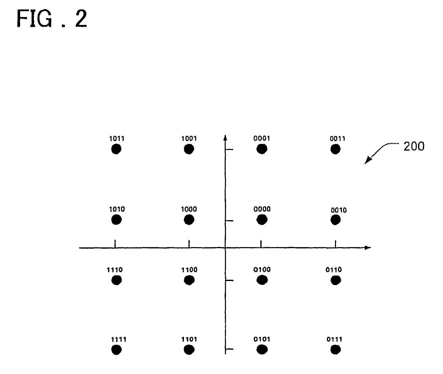
[0040]A first example of the present invention will be described in the context of a signal modulated using 16-QAM. FIG. 2 depicts the square 16-QAM constellation. The constellation 200 has an index m=2 and is defined to be a signal constellation with 4m points. The square 16-QAM constellation shown in FIG. 2 has an index m=2 and is defined to be a signal constellation with 4m points. Each signal point is denoted by its index (i,j) where 0≦i,jm. The position of each i,j point on the constellation is given by the following formula:

[0041]Ci,j={(2m-1-2⁢i)⁢Δ,(2m-1-2⁢j)⁢Δ}whereΔ=34m-1⁢(12).

[0042]The above formula ensures that the average energy of the signal constellation is normalised to one, where Δ is a normalisation parameter for a square-QAM constellation. For a 16-QAM constellation, m=2 and

[0043]Δ=110.

For other square-QAM constellations, the value of both m and Δ will change. Accordingly, for a 64-QAM constellation, m=3 and

[0044]Δ=142,

whilst for a 256-QAM constellation, m=4 and

[004...

example 2

[0063]The present Invention can be realized with higher order modulation schemes such as 64-QAM. Generally speaking the process followed in this case is the same as for 16-QAM, with the following changes:[0064]As noted above, more thresholds are calculated.[0065]For 64-QAM a different set of constellation reference symbols is used, meaning that a different grey code is needed. This necessitates the use of a different set of criteria for determining the core symbol in step 308. For 64-QAM, given the constellation definition as shown in FIG. 5, the 6 bits for the core symbol (b0-b5) are determined using the following criteria:

[0066]

TABLE 2Criteria for determining core symbol with 64-QAMb0b1b2If y_i ≧ 0If y_q ≧ 0If abs(z_i) ≦ T2b0 = 0b1 = 0b2 = 0ElseElseElseb0 = 1b1 = 1b2 = 1b3b4b5If abs(z_q) ≦ T2If T1 ≦ abs(z_i) ≦ T3If T1 ≦ abs(z_q) ≦ T3b3 = 0b4 = 0b5 = 0ElseElseElseb3 = 1b4 = 1b5 = 1[0067]A different look up table is needed for determining which surrounding reference symbols are to b...


PUM


Abstract

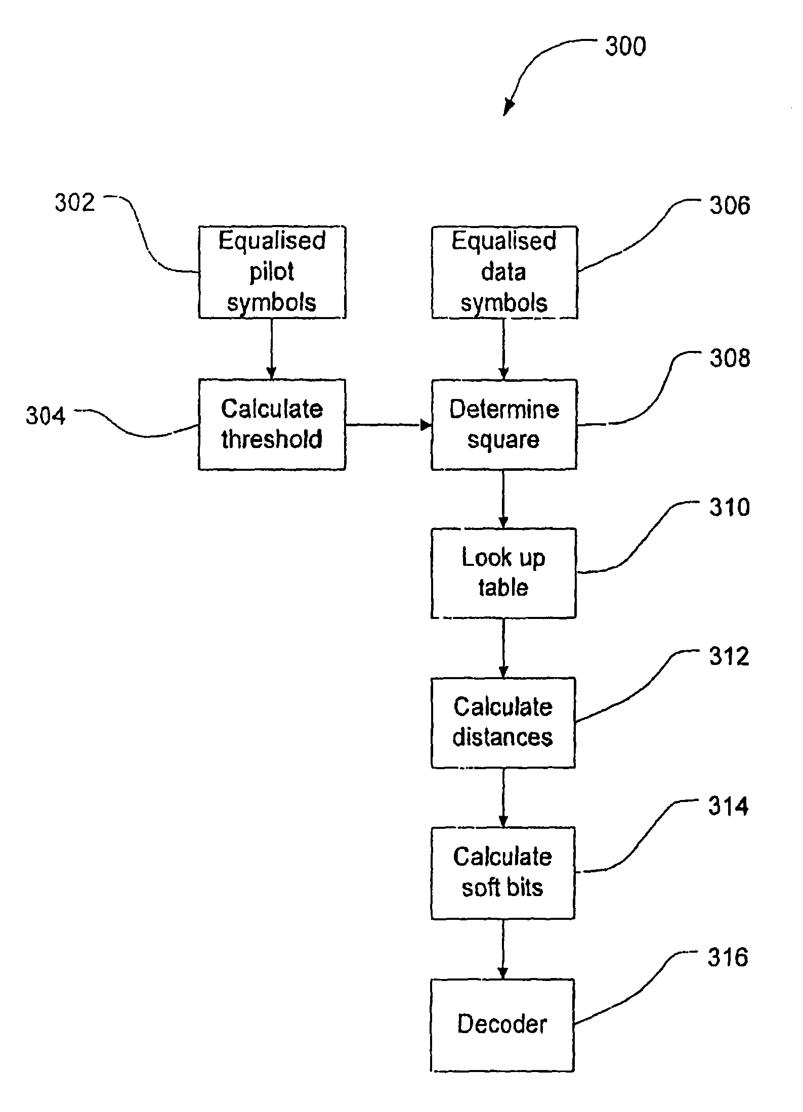
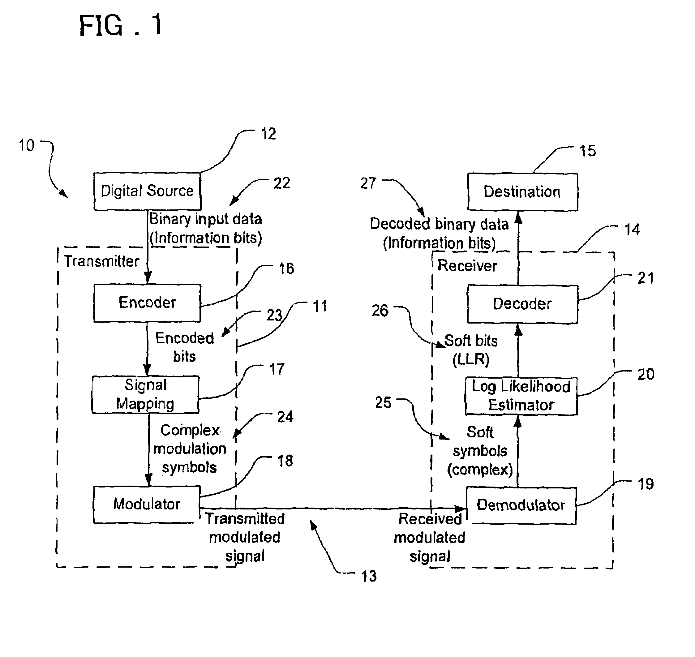
A method of calculating at least one soft bit corresponding to a data symbol received by a radio receiver is described. In one form the method (300) includes, calculating an average amplitude at least one received data symbol. The method also includes calculating (304) at least one threshold amplitude in respect of the data symbol on the basis of the calculated average amplitude. Next a subset of constellation symbols is determined (310) at least partly on the basis of the at least one threshold, and for which a distance determination will be made. The distance between the position of the data symbol and each of the symbols in the subset of constellation symbols is determined (312) and then a soft bit corresponding to the received symbol is calculated (314) on the basis of said determined distances.

Description

REFERENCE TO RELATED APPLICATION[0001]This application is based upon and claims the benefit of the priorities of Australian provisional patent application No. 2006905197 filed on 20 Sep. 2006 and Australian standard patent application filed on 31 Aug. 2007, the disclosures of which are incorporated herein in their entirety by reference thereto.FIELD OF THE INVENTION[0002]The present invention relates to methods of demodulation used in a receiver in a wireless communications network, and a device and program therefor.[0003]It is convenient to describe the preferred examples in connection with a system that uses turbo code and quadrature amplitude modulation (QAM). However the present invention should not be considered as being limited to the use of turbo code, but should be considered as being generally applicable to systems using any type of channel encoder such that the corresponding decoder uses soft inputs to recover the transmitted information bits.BACKGROUND OF THE INVENTION[00...

Claims


Application Information

Patent Timeline
Patent Type & Authority Patents(United States)
IPC IPC(8): H04L27/06
CPCH04L25/067H04L27/38H04L27/3845
Inventor BUI, THANHSIEW, JIUN
Owner LENOVO INNOVATIONS LTD HONG KONG
Why Eureka
Eureka Blog
Learn More