Vehicle Transformer
- Summary
- Abstract
- Description
- Claims
- Application Information
AI Technical Summary
Benefits of technology
Problems solved by technology
Method used
Image
Examples
embodiment 1
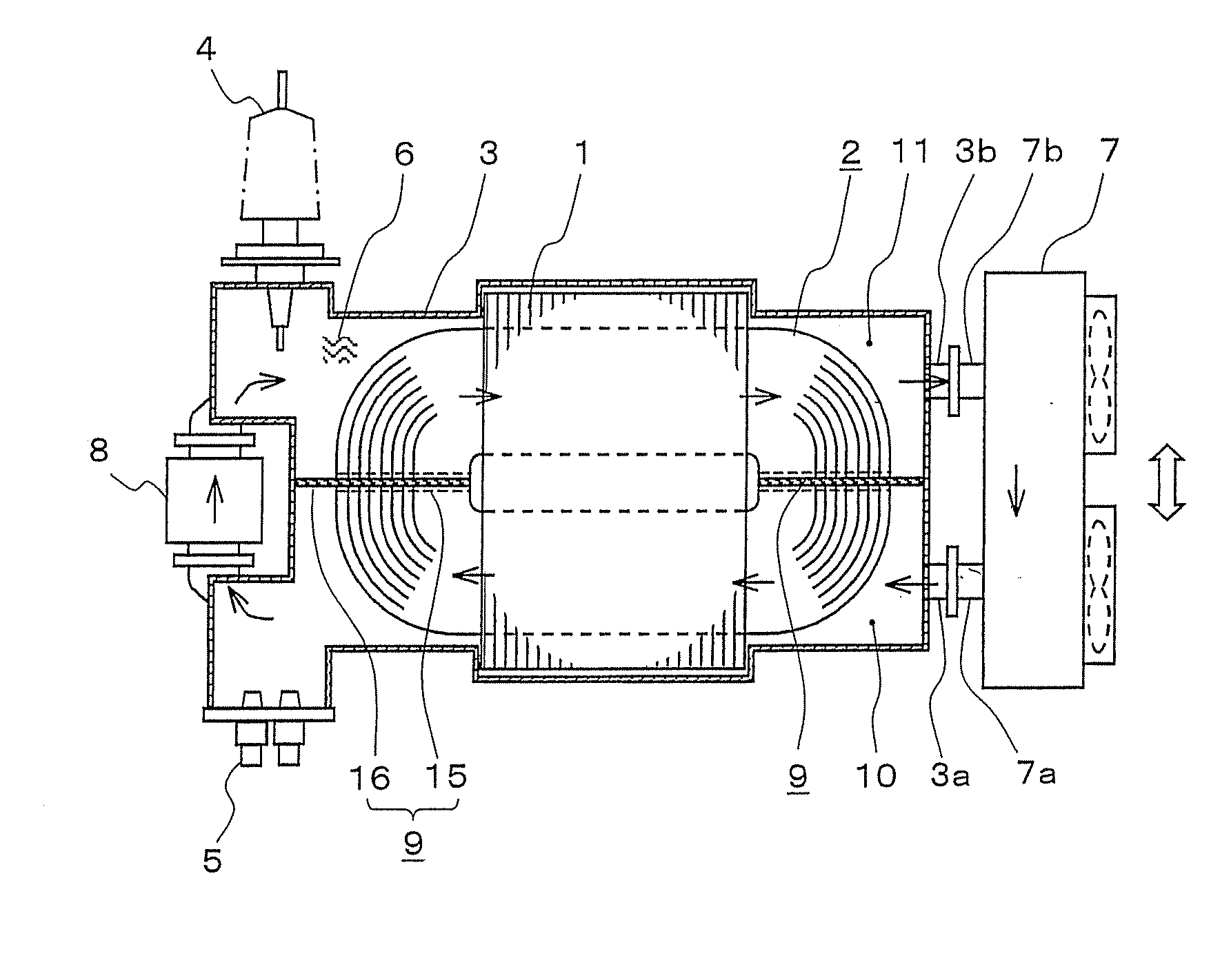
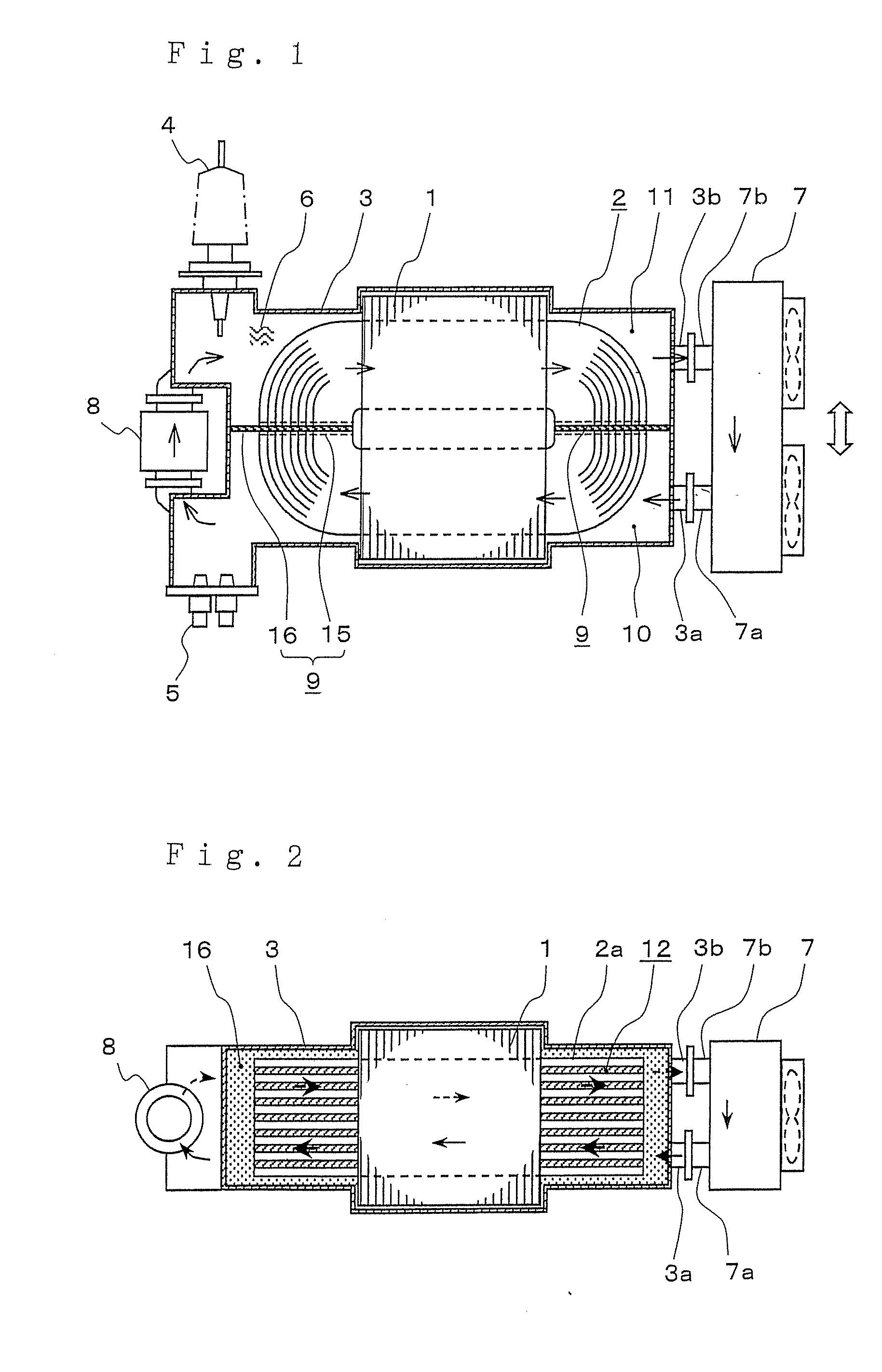
[0020]FIG. 1 is a plan sectional view showing an internal structure of a vehicle transformer according to embodiment 1, and FIG. 1 is an internal structure diagram seen from the floor of a vehicle toward the ground side and a thick arrow shows the traveling direction of the vehicle. FIG. 2 is a front sectional view showing a section of the center part seen from the side of FIG. 1. The vehicle transformer is mounted under the floor of the vehicle so that the orthogonal direction to the paper surface in the front sectional view of FIG. 2 may be the traveling direction of the vehicle. As below, the configuration will be explained according to the drawings.
[0021]A core 1 is a three-leg core with laminated thin steel plates, and a high-tension and low-tension winding 2 is wounded around its center leg. The winding 2 is configured by preparing a plurality of coil plates 2a formed by winding a rectangular wire (or circular wire) into an oval shape in the plan view, and alternately stacking...
embodiment 2
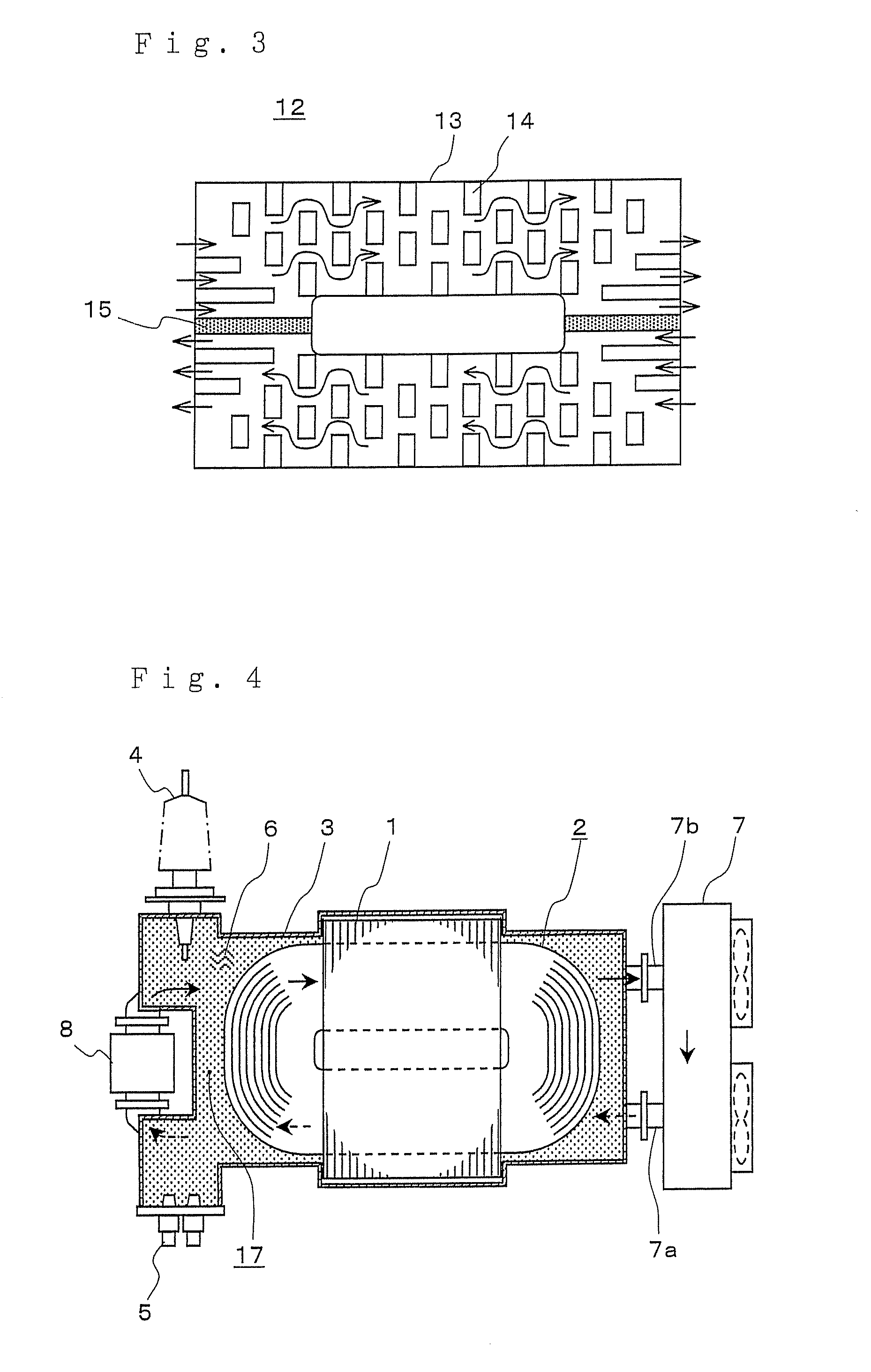
[0039]FIG. 4 is a plan sectional view showing an internal structure of a vehicle transformer according to embodiment 2, and FIG. 5 is a front sectional view showing a section of the center part of FIG. 4.
[0040]The vehicle transformer of embodiment 2 is basically equal to the vehicle transformer of embodiment 1 except that the insertion direction of the partition member is different, and the same signs are assigned to the equal parts and the description thereof will be omitted. The description will be made centering on the difference.
[0041]As shown in FIGS. 4, 5, a partition member 17 of embodiment 2 is inserted in parallel to the coil plate 2a surface of the winding 2 nearly at the center part of the winding 2 in the vertical direction to be horizontal when the vehicle transformer is mounted on a vehicle. As described using FIG. 5, the interior of the tank 3 is vertically divided into two by the partition member 17, and a first cooling medium channel 18 is formed at the lower side a...
embodiment 3
[0046]FIG. 7 is a plan sectional view showing an internal structure of a vehicle transformer according to embodiment 3,and FIG. 8 is a front sectional view showing a section of the center part of FIG. 7.
[0047]The same signs are assigned to the equal parts to those in FIG. 1 and FIG. 2 of embodiment 1 and the description thereof will be omitted, and the description will be made centering on the difference.
[0048]The difference is in that the attachment structure of the cooling unit to the tank. Further, a cooing unit 23 of embodiment 3 shows a self-cooling type. That is, cooling is performed utilizing traveling wind occurring during traveling of a vehicle (shown by a thick arrow in FIG. 7).
[0049]Embodiment 3 is characterized in that the surface of the tank 3 at the side where the inlet and outlet of the cooling medium are provided in embodiment 1 or 2 is also used as an attachment surface to which the cooling unit 23 is directly attached and an attachment flange 22 is provided. In the...
PUM
 Abstract
Description
Claims
Application Information
 - R&D
- Intellectual Property
- Life Sciences
- Materials
- Tech Scout
- Unparalleled Data Quality
- Higher Quality Content
- 60% Fewer Hallucinations
Browse by: Latest US Patents, China's latest patents, Technical Efficacy Thesaurus, Application Domain, Technology Topic, Popular Technical Reports.
© 2025 PatSnap. All rights reserved.Legal|Privacy policy|Modern Slavery Act Transparency Statement|Sitemap|About US| Contact US: help@patsnap.com


