
Real-time video signal interweaving for autostereoscopic display

a real-time video signal and display system technology, applied in the field of real-time autostereoscopic display systems, can solve the problems of requiring a large capacity, bulky display subsystems, and requiring precise alignment of display devices, so as to achieve efficient storage space

Inactive Publication Date: 2009-10-22
ROTEM GAL +2
View PDF10 Cites 6 Cited by
  • Summary
  • Abstract
  • Description
  • Claims
  • Application Information

AI Technical Summary

Benefits of technology

[0029]The qualifier “real-time” in the present context refers to the ability of the system to produce any number of consecutive interwoven video frames at the same average rate at which sets of projection-image video frames are obtained—thus obviating the need to store more than one set of frames at any time. This also means that the interwoven video signal (which is ready to be fed to the display device) is obtained at a delay from the corresponding projection video signals that does not exceed one frame time. It is noted that in practice the delay is considerably shorter than one frame time.
[0030]In some configurations of the system according to the invention the interwoven video signal is fed directly to one or more autostereoscopic display devices. Their advantage over prior art lies in the ability to display the image of the object on active-matrix devices immediately. In other configurations of the system according to the invention the interwoven video signal is fed to a storage system, whence it can be retrieved at a later time and fed to autostereoscopic display devices. Their advantage over prior art lies in the ability to display the stored video signal directly upon retrieval obviating the process of combining the signals of projection images Another advantage of the latter configurations lies in the ability to store the images in the interwoven video format, which is more compact and thus more efficient in storage space than the format of the original projection images. Other configurations of the system according to the invention provide outputs both directly to display devices and to storage devices.

Problems solved by technology

The display subsystems thus disclosed have the disadvantages of being bulky and of requiring precise alignment of the display devices relative to each other and to the screen.
A further disadvantage is that if the scene need to be recorded for future display, a plurality of video signals must be stored, which may require a commensurate large capacity.
The process of preparing such images, from either source, for display on such autostereoscopic devices is relatively lengthy and therefore is not carried out in real-time (relative to changes in the scene).
For this reason there are currently no active-matrix-based autostereoscopic imaging systems available that can capture, in real time and simultaneously, a plurality of sequences of projection-images of a changing real scene, the sequences being unlimited in duration.
As noted above, projection-type autostereoscopic systems, such as disclosed in the aforementioned patents, though amenable to real-time imaging, are cumbersome and also require large storage capacity for any intermediate storage of image sequences.

Method used


Image

  • Real-time video signal interweaving for autostereoscopic display
  • Real-time video signal interweaving for autostereoscopic display
  • Real-time video signal interweaving for autostereoscopic display

Examples


Embodiment Construction

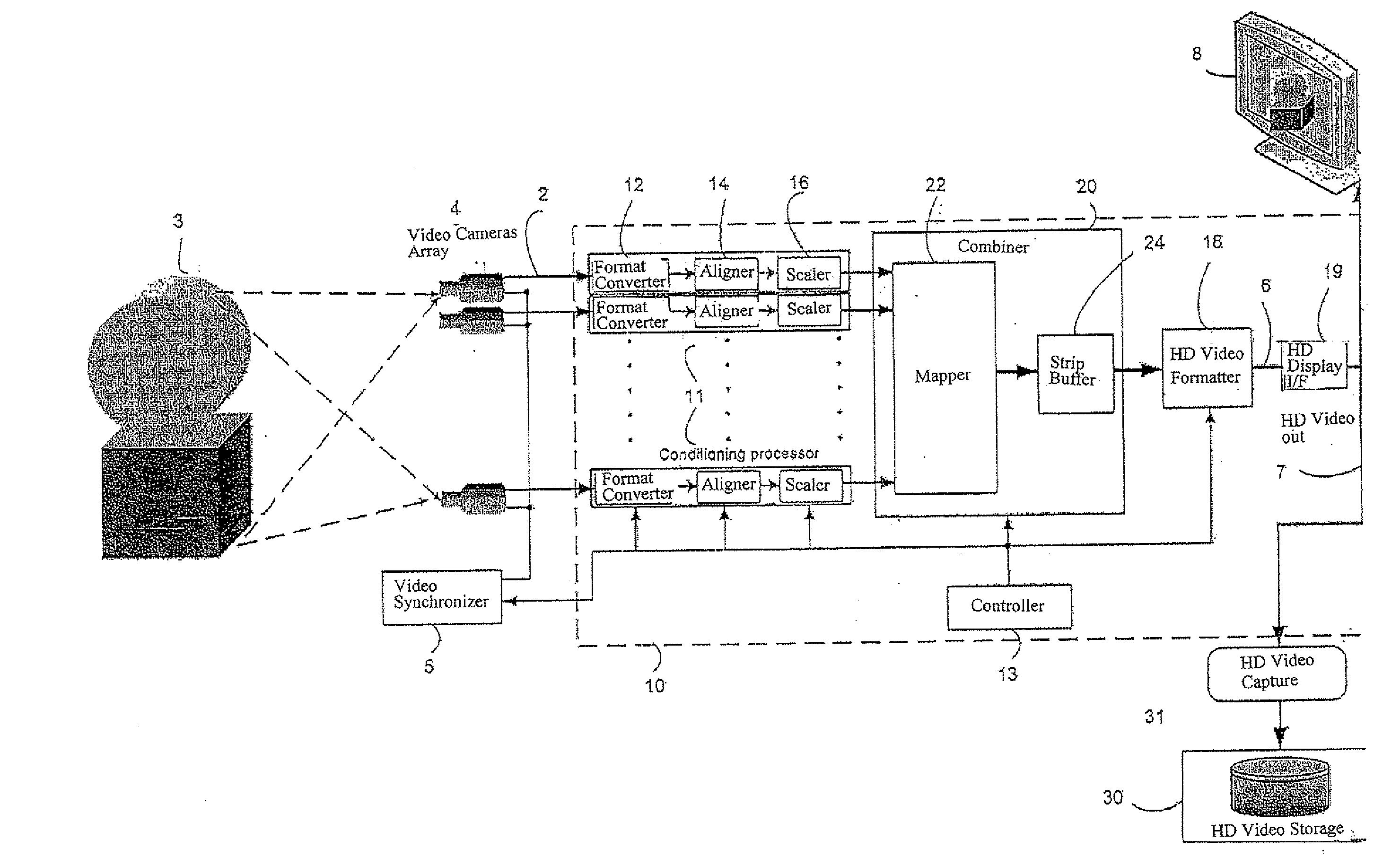
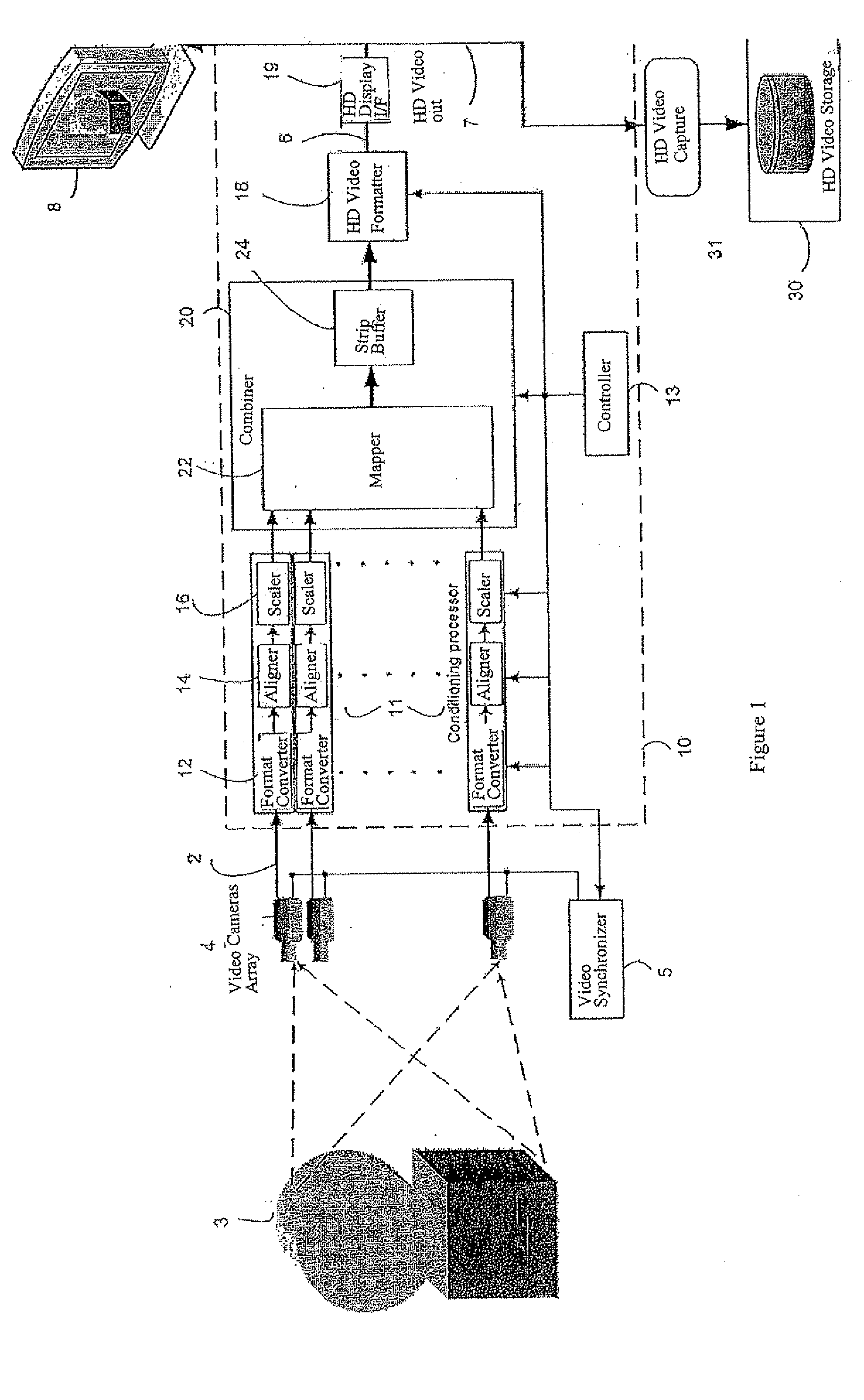
[0035]FIG. 1 depicts, in a schematic block diagram, a preferred embodiment of the invention in a typical configuration. Real-time Multiview Video to Autostereoscopic Display Converter (RMVADC) 10 accepts a plurality of video signals 2 and converts them, in real time, to a high-definition (HD) video signal 6 that is applicable to an autostereoscopic display device 8. The plurality of video signals 2, which may be in any suitable format, represent views, or projection images, of an object or a scene 3 (the two terms to be used interchangeably) from respective directions and are accordingly referred to herein as projection video signals. They usually arrive simultaneously from one or more video sources. In the configuration depicted in FIG. 1 the video sources are respective video cameras 4, disposed at certain distances from each other and so as to image the object 3 from respective directions. The video sources are, however, not part of the invention and may, in general, be of any ty...


PUM


Abstract

A method, apparatus and system for simultaneously capturing a plurality of video signals that carry images of a changing real three-dimensional scene, taken from respective different directions, and for combining them, in real time, into an interwoven video signal, ready to be fed to an active-matrix-based autostereoscopic display device.

Description

FIELD OF THE INVENTION[0001]The field of the invention is autostereoscopic display systems and, in particular, systems for real-time autostereoscopic imaging of changing real scenes.BACKGROUND[0002]By the term autostereoscopy we mean, generally, the display of a virtual three-dimensional image of an object or a scene (the two terms to be used interchangeably), based on a plurality of two-dimensional images (to be referred to as “projection images”) that represent projections of the object to, or views of the object from, corresponding different directions, spread in a horizontal plane. The display allows viewing the virtual image from a plurality of directions, corresponding to and usually similar to, those of the projection images. The projection directions, and therefore also the viewing directions, are usually chosen so that at a normal viewing distance they correspond to the inter-ocular distance. They thus enable, upon binocular viewing from any of the available viewing directi...

Claims


Application Information

Patent Timeline
Patent Type & Authority Applications(United States)
IPC IPC(8): H04N13/02
CPCH04N13/0029H04N13/004H04N13/0409H04N13/0402H04N13/0404H04N13/0242H04N13/139H04N13/156H04N13/243H04N13/302H04N13/305H04N13/31
Inventor ROTEM, GALSHEFER, OFIR
Owner ROTEM GAL
Learn More