Scanning member with flexible pressing member

a technology of flexible pressing member and scanning device, which is applied in the direction of electrographic process apparatus, thin material processing, instruments, etc., can solve the problems of deteriorating the scan quality of the resulting images, affecting the scanning process, and inevitably increasing the manufacturing cost, so as to achieve the effect of adjusting the distance between the document and the transparent platen

Active Publication Date: 2009-10-22
AVISION
View PDF9 Cites 7 Cited by
  • Summary
  • Abstract
  • Description
  • Claims
  • Application Information

AI Technical Summary

Benefits of technology

[0007]It is therefore an object of the invention to provide a scanning device having a flexible pressing member, disposed upstream of a scan zone or within the scan zone, for pressing a document and for effectively adjusting the distance between the document and the transparent platen. Thus, the documents of different thicknesses can be pressed and transported along the transparent platen more adaptively.

Problems solved by technology

In this case, the roller and the scan platen tend to wear off because of the frictional contact there between, which consequently deteriorates the scan quality of the resulting images.
In addition, when a thicker sheet of the document is being scanned, the document may not enter the gap between the roller and the scan window for the gap width being smaller than the thickness of the sheet, such that a paper jam may occur and interrupt the scan procedure.
However, this mechanism requires more components and the longer assembling time, and the manufacturing cost is inevitably increased.

Method used


Image

  • Scanning member with flexible pressing member
  • Scanning member with flexible pressing member
  • Scanning member with flexible pressing member

Examples


first embodiment

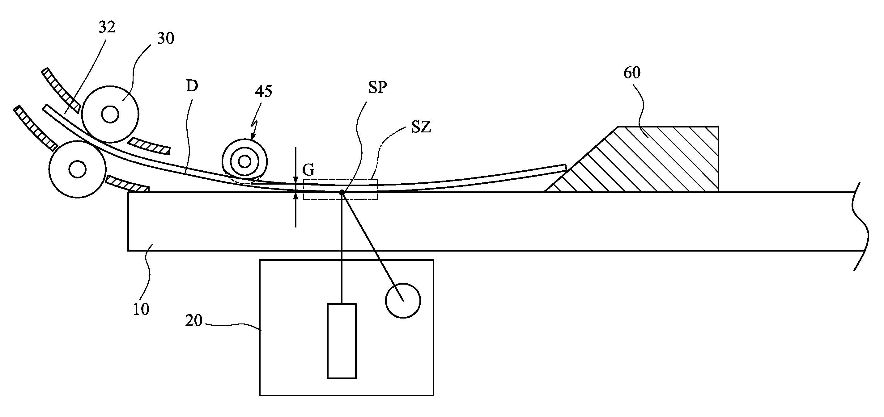
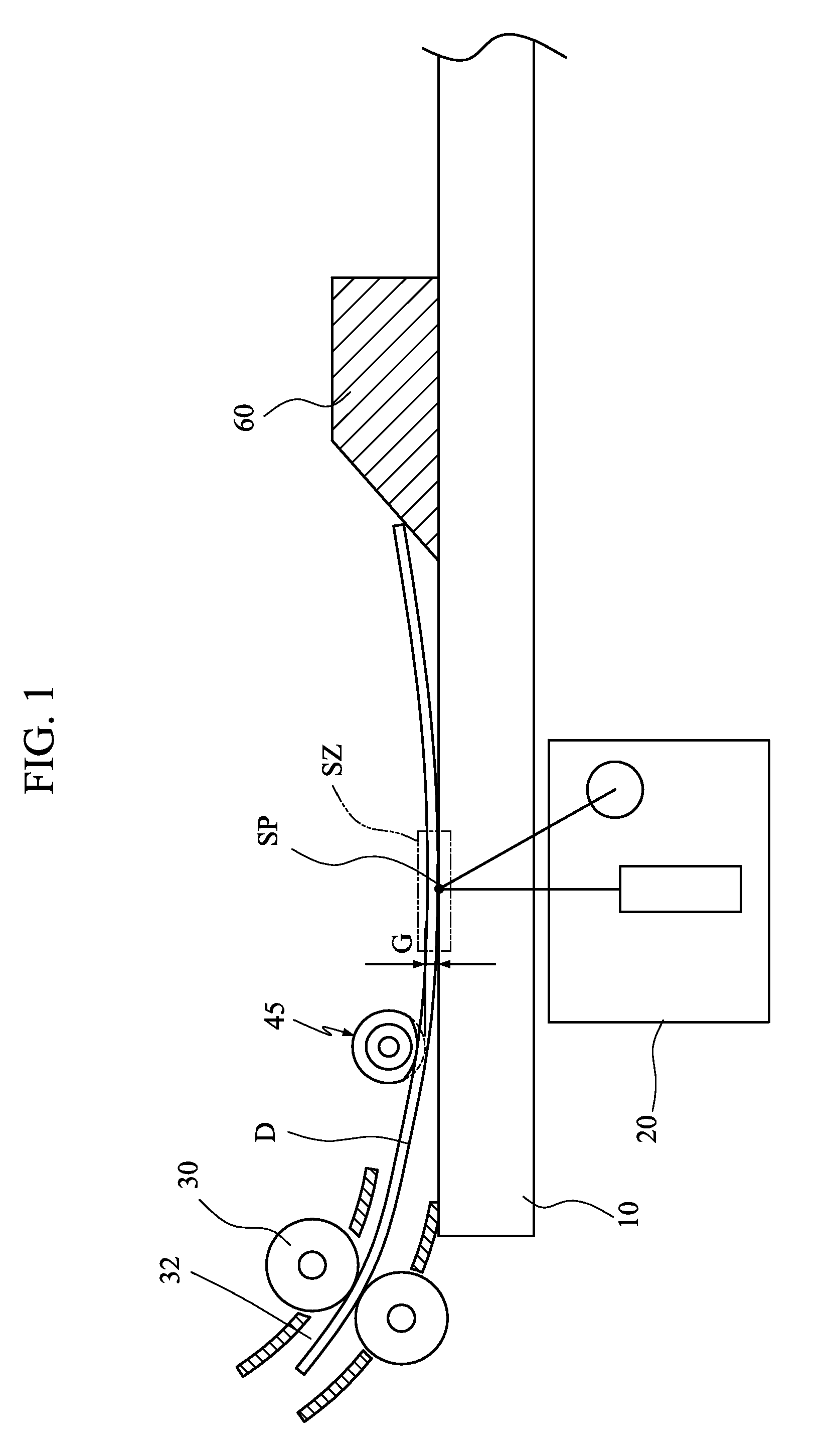
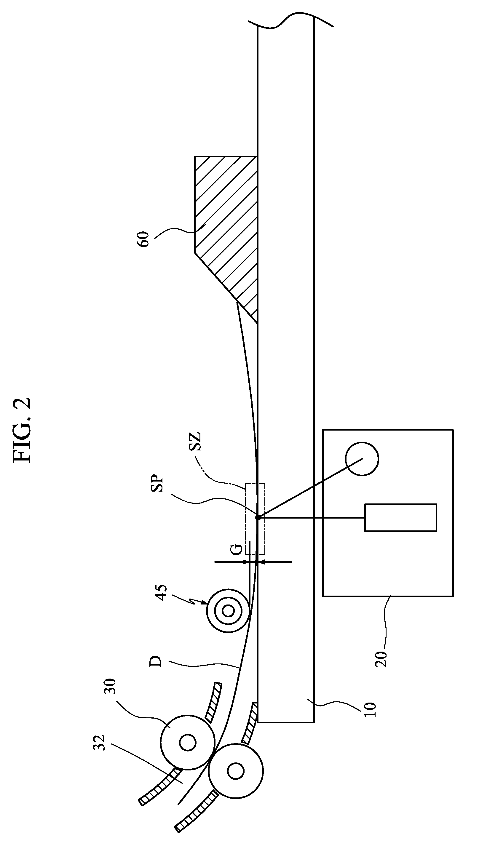
[0021]FIGS. 1 and 2 are schematic illustrations showing two states of a scanning device according to the invention. Referring to FIG. 1, the scanning device of this embodiment includes a transparent platen 10, a scanning module 20, a document transporting mechanism 30 and a flexible pressing member 45.

[0022]The scanning module 20 located in a scan zone SZ acquires through the transparent platen 10 an image of a document D. The document transporting mechanism 30 transports the document D along a passageway 32 and across the scan zone SZ.

[0023]The flexible pressing member 45 is disposed in the passageway 32 and upstream of the scan zone SZ (see FIG. 1) or within the scan zone SZ (see FIG. 11). The upstream side is defined based on the direction of transporting the document D. Thus, the document D is firstly transported past the flexible pressing member 45 and then the scan zone SZ. The flexible pressing member 45 is located apart from the transparent platen 10 by a gap G. wherein the ...

sixth embodiment

[0040]FIG. 11 is a schematic illustration showing a scanning device according to the invention. As shown in FIG. 11, the flexible pressing member 45 is disposed in the passageway 32 and in the scan zone SZ.

[0041]According to the embodiments of the invention, the flexible pressing member, disposed upstream of the scan zone or within the scan zone, may be provided to press the document, and the flexible pressing member separated from the transparent platen by a gap is configured to be deformable. Thus, the flexible pressing member can adaptively press the documents of different thicknesses against the transparent platen in the scan zone. On the other hand, the invention also adopts the downstream pressing member disposed on the downstream side to press the document so that the friction between the pressing element and the transparent platen can be reduced, and the distance between the document and the transparent platen can be effectively controlled.


PUM


Abstract

A scanning device includes a transparent platen, a scanning module, a document transporting mechanism and a flexible pressing member. The scanning module is located in a scan zone and acquires through the transparent platen an image of a document. The document transporting mechanism transports the document along a passageway and across the scan zone. The flexible pressing member is disposed in the passageway, upstream of the scan zone or within the scan zone and located apart from the transparent platen by a gap. The flexible pressing member is deformed in a direction away from the transparent platen due to a force applied by the document transported across the scan zone.

Description

[0001]This application claims priority of No. 097114409 filed in Taiwan R.O.C. on Apr. 21, 2008 under 35 USC 119, the entire content of which is hereby incorporated by reference.BACKGROUND OF THE INVENTION[0002]1. Field of Invention[0003]The invention relates to a scanning device, and more particularly to a scanning device having a flexible pressing member for pressing documents having different thicknesses. The flexible pressing member may be deformed and is arranged such that it is located apart from a transparent platen of the scanning device by a gap.[0004]2. Related Art[0005]In a conventional automatic document feeder, rollers are usually adopted to transport a document onto a scan platen so that a scanning module disposed below the scan platen can capture an image of the document. The depth of field for the image sensor employed in the scanning module is critical to the scan quality of the images generated. Greater the depth of field the image sensor has, the greater tolerance...

Claims


Application Information

Patent Timeline
Patent Type & Authority Applications(United States)
IPC IPC(8): H04N1/04
CPCH04N1/121H04N1/193H04N1/1235H04N1/1225
Inventor SHENG, THOMAS
Owner AVISION
Why Eureka
Try Eureka