Fluid Discharge Apparatus and Method of Use

a technology of fluid discharge apparatus and discharge valve, which is applied in the direction of valve operating means/release devices, wellbores, pipelines, etc., can solve the problems of reducing the effective inner diameter of the conduit, and affecting the flow ra

Active Publication Date: 2019-01-24
PARADIGM FLOW SERVICES
View PDF57 Cites 5 Cited by
  • Summary
  • Abstract
  • Description
  • Claims
  • Application Information

AI Technical Summary

Benefits of technology

[0018]Preferably, the valve arrangement is operable to cycle between the first condition and the second condition under the effect of a pressurised fluid entering the body from the inlet. Preferably, the valve arrangement is operable to be passively operated, without external intervention or operation, such that a pressurised fluid source causes the valve arrangement to cycle between the first condition and the second condition to provide an interrupted flow of fluid through the body.

Problems solved by technology

During hydrocarbon production and transportation operations, it is common for the interiors of fluid conduits, including pipelines, wellbores, risers and umbilicals, to become fouled.
This fouling can lead to the build-up of layers of debris, scale or particulate matter on the inside of conduits, which reduces the effective inner diameter (ID) of the conduit and reduces the flow rate.
Fouling may also produce blockages in the conduits which completely prevent fluid flow through the conduits.
In addition, sand and other particulate matter may be produced from the formation and accumulate inside the production tubing and may partially or completely block fluid flow through the production tubing, decreasing the production rate and the efficiency of the well.
The coiled tubing injector system described above is a substantial and heavy piece of equipment, with large footprint and high capital expense.
This limits the number of installations where coiled tubing operations can be performed and can make operations more costly.
These problems are particularly significant in the case of offshore operations, for example in a turret of a floating production storage production and offloading vessel (FPSO) where space is at a premium and cranes are unable to lift the components into place.
Even light coiled tubing units which are used onshore are still substantial pieces of equipment which are large in size and weight in the context of offshore operations.
Other considerations limit the applications of coiled tubing.
Firstly, blockages and restrictions can occur in narrow bore fluid conduits, which are simply too small to receive coiled tubing.
However, this rigidity also has drawbacks that make coiled tubing interventions unsuitable for some applications.
For example, it may not be possible to inject coiled tubing into a fluid conduit which has a deviated or convoluted path.
In extreme cases, the rigid coiled tubing may not be able to pass through some curved or bent pipeline systems.
Even where passage is possible, the frictional resistance between the coiled tubing and the inside wall of the wellbore will limit the depth to which the coiled tubing can be deployed.
For the foregoing reasons, the wellbore cleanout systems according to the prior art are generally unsuitable for applications other than the cleaning of wellbores.
While the flexible hose systems of WO2012 / 140432 and WO2014 / 102549 address deployment issues associated with convoluted paths and increasing depth or reach of the equipment, they are limited in their ability to discharge fluid with sufficient jetting power to forcibly dislodge or loosen material such as debris or scale from a pipeline wall at significant depths or reaches.
One factor limiting jetting power for any fluid conduit system is the frictional losses in the pumped fluid as it flows in the hose.

Method used


Image

  • Fluid Discharge Apparatus and Method of Use
  • Fluid Discharge Apparatus and Method of Use
  • Fluid Discharge Apparatus and Method of Use

Examples


Embodiment Construction

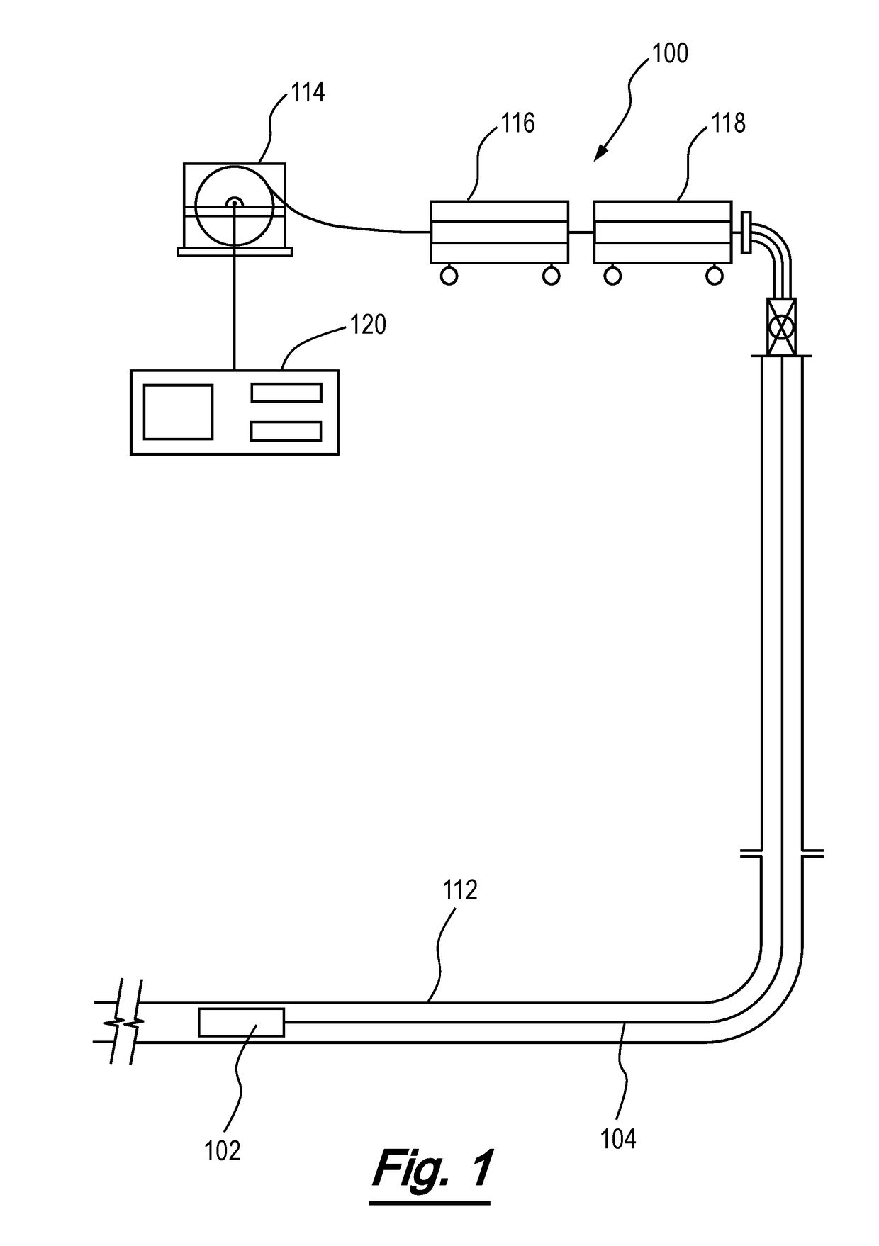
[0044]The invention has application to cleaning operations for subsea pipelines, including blockage and / or debris removal, and is particularly advantageous in cleaning operations in which the pipeline is accessed from surface via a marine, catenary and / or flexible riser. Accordingly, the invention will be described in the context of such an operation by way of example only.

[0045]Referring firstly to FIG. 1, there is shown a system according to an embodiment of the invention, generally depicted at 100. System 100 is formed from a fluid discharge apparatus 102 and a flowline 104, which in this case is a flexible hose. The apparatus 102 and flexible hose are shown here in situ in a fluid conduit 112, which in this case is a subsea pipeline accessed by a production riser. The apparatus 102 and the flexible hose 104 are deployed from a storage reel 114 via an injector unit 116 and a pressure control device 118, comprising a stripper and blowout preventer (BOP) unit.

[0046]The injector uni...


PUM


Abstract

The invention provides a fluid discharge apparatus (102) and a method of use. The apparatus (102) comprises a body (106) comprising an inlet (122) configured to receive fluid from a fluid source, and one or more fluid discharge ports (140). A valve arrangement (124) in the body (106) is operable to be cycled to provide an interrupted flow of fluid through the body (106). The valve arrangement (124) may be disposed in the body (106), and/or may be operable to be moved between a first condition in which fluid entering the body (106) from the inlet (122) is prevented from passing through the apparatus (102), and a second condition in which fluid is discharged through the one or more fluid discharge ports (140). The valve arrangement (124) may be operable to cycle between the first condition and the second condition to provide an interrupted flow of fluid through the body (106).

Description

[0001]The present invention relates to a fluid discharge apparatus and a method of use, and in particular to a fluid discharge and apparatus for method of use in the cleaning and / or jetting of fluid conduits. The invention relates generally to fluid conduits and pipelines across a range of industries. Aspects of the invention relate to applications in the hydrocarbon exploration, production and transportation industry, and in particular to methods of jetting deposits and other materials from hydrocarbon pipeline systems.BACKGROUND TO THE INVENTION[0002]During hydrocarbon production and transportation operations, it is common for the interiors of fluid conduits, including pipelines, wellbores, risers and umbilicals, to become fouled. This fouling can lead to the build-up of layers of debris, scale or particulate matter on the inside of conduits, which reduces the effective inner diameter (ID) of the conduit and reduces the flow rate. Fouling may also produce blockages in the conduits...

Claims


Application Information

Patent Timeline
Patent Type & Authority Applications(United States)
IPC IPC(8): E21B34/14E21B37/00E21B34/10
CPCE21B2034/007E21B34/14E21B37/00E21B34/10E21B21/103E21B37/08E21B2200/06F16K31/58
Inventor THOMSON, ASHLEYVARDY, ALAN
Owner PARADIGM FLOW SERVICES
Why Eureka
Try Eureka