Infrared ray switching device

a switching device and infrared ray technology, applied in the direction of optical radiation measurement, instruments, pulse technique, etc., can solve the problems of unstable performance of conventional capacitance switches, unstable performance of body temperature switches, and unsatisfactory reliability, and achieve the effect of effective operation distan

Inactive Publication Date: 2009-07-28
A A A BEAUTY SUPPLY CO LTD
View PDF4 Cites 6 Cited by
  • Summary
  • Abstract
  • Description
  • Claims
  • Application Information

AI Technical Summary

Benefits of technology

[0012]The present invention has advantages of switching the apparatus by touching. Furthermore, the small dimensions, capable of applying in any place, and an effective operation distance is adjustable according to one of the adjustable emission power and the adjustable reception power.

Problems solved by technology

Because of the disadvantages, the performance of the conventional capacitance switch is unstable, and the reliability is not ideal.
If the distance is less than 1 m, the performance of the body temperature switch is unstable, and the reliability is getting worse.
In the next place, the body temperature switch is only able to switch on and switch off, and is unable to switch gradually for the limitation of the sensor.
Furthermore, the body temperature switch is disadaptive for an environment with surrounding heat sources, because some error may be caused by the heat sources.
During transmitting through air, the speed of transmission is slow, and the transmission is tended to be influenced by the air density and the temperature and thus it results in low reliability during the period of transmission.
The scale of the ultrasonic transducer is large for being restrained by the character of the sound wave, and is unsuitable for a small scale requirement of the switch.
On the other hand, there is a diffraction problem of the sound wave needed to be dealt with when the ultrasonic transducer is applied within a distance less than 10 cm.

Method used


Image

  • Infrared ray switching device
  • Infrared ray switching device
  • Infrared ray switching device

Examples


first embodiment

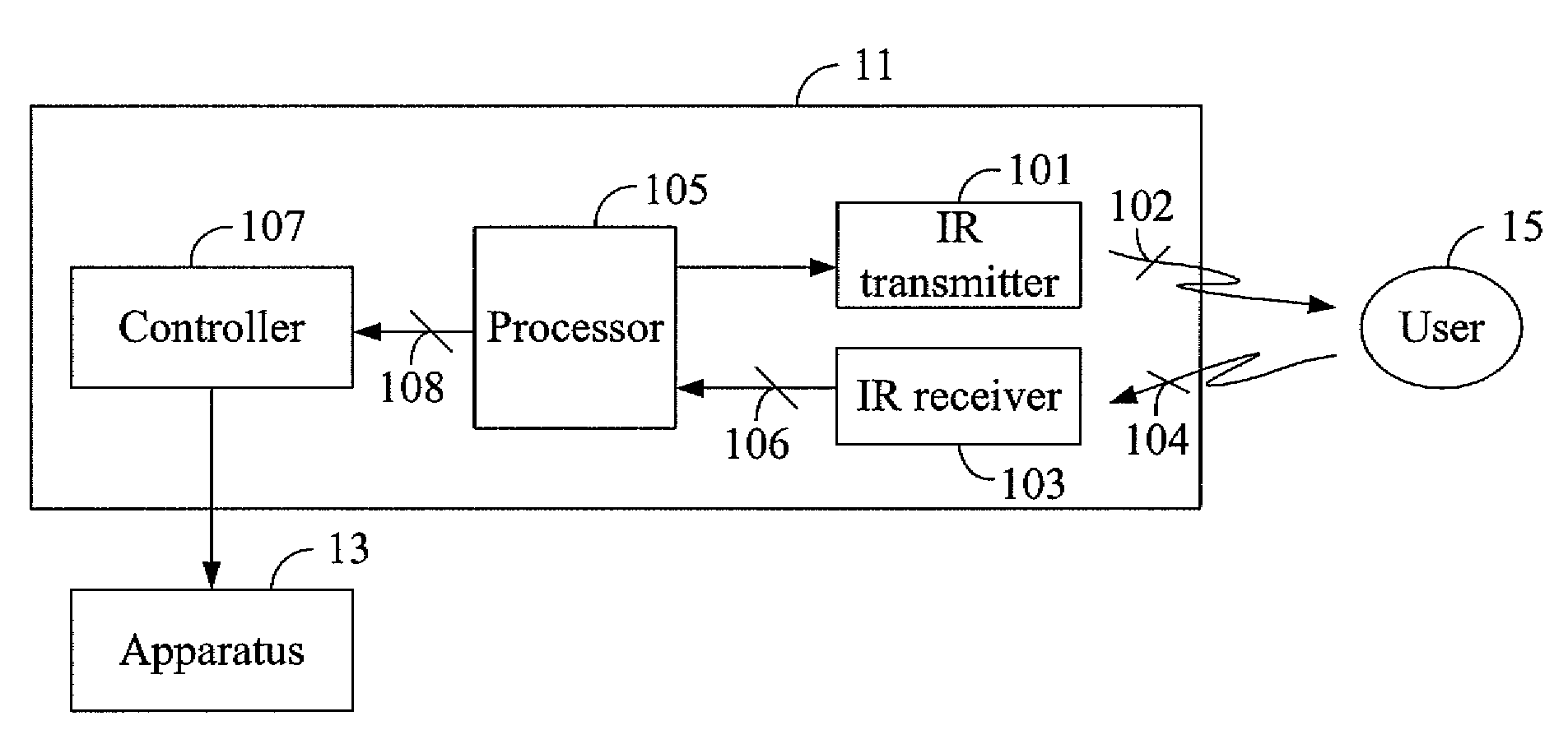
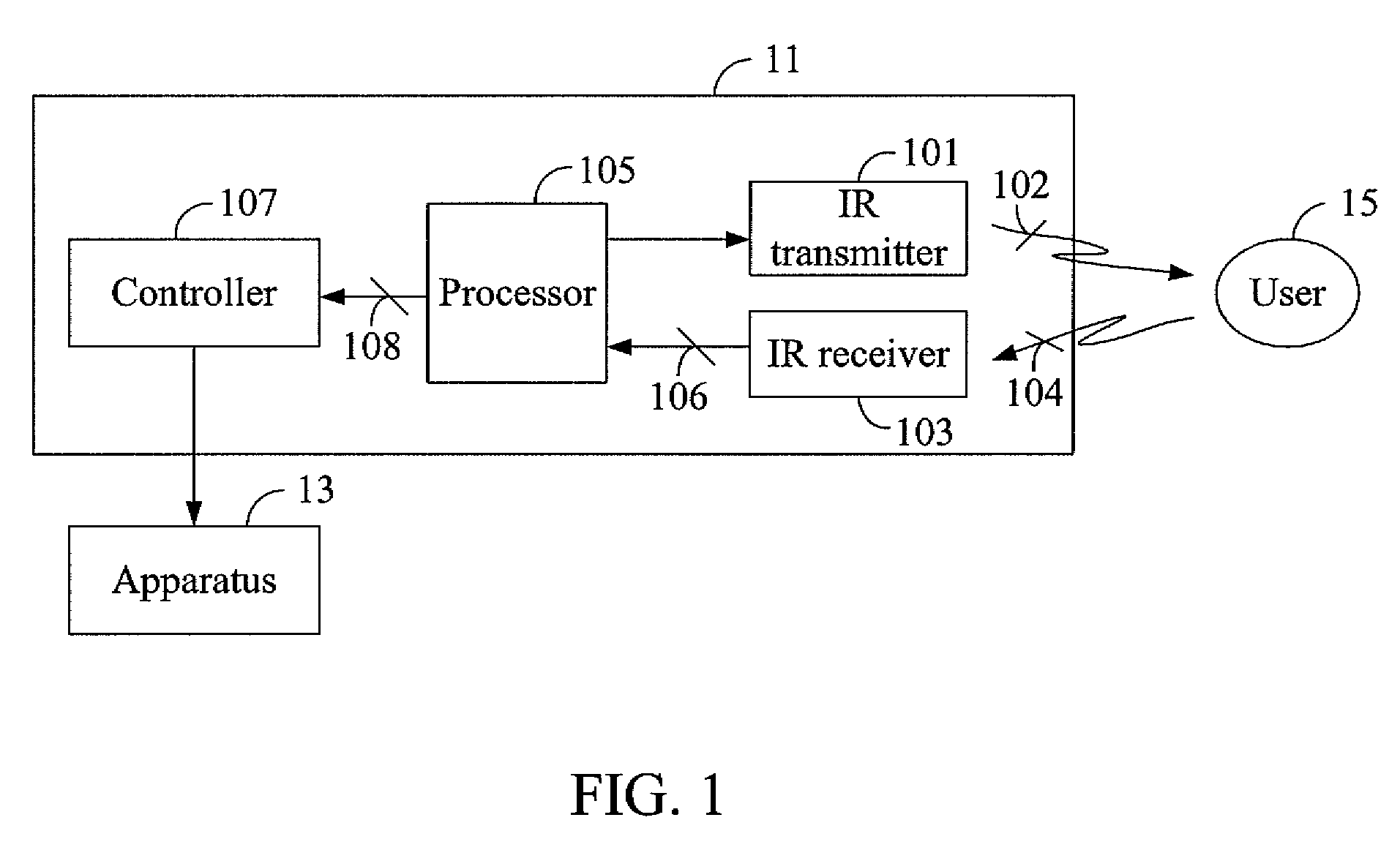
[0017]the present invention is an infrared ray (IR) switching device 11, as shown in FIG. 1, electrically connected to an apparatus 13. The IR switching device 11 comprises an IR transmitter 101, an IR receiver 103, a processor 105, and a controller 107. The IR transmitter 101 is configured to emit an IR signal 102 with an emission power. The IR signal 102 is a high frequency signal with intervals, i.e. a high frequency carrier. Specially, the emission power of the IR signal 102 is adjustable. To cooperate with a requiring operation distance, especially in a short distance such as 1 cm to 100 cm, the emission power could be adjusted to a suitable value for precision control. The IR receiver 103 is configured to receive a reflected IR signal 104 to generate a response signal 106. Moreover, a high frequency portion of the reflected IR signal 104 is rejected when generating the response signal 106. The reflected IR signal 104 is generated after the IR signal 102 is reflected and the re...

second embodiment

[0023]the present invention is an IR switching device 11, electrically connected to an apparatus 13, referring to FIG. 1 as well. The IR switching device 11 comprises an IR transmitter 101, an IR receiver 103, a processor 105, and a controller 107. The IR transmitter 101 is configured to emit an IR signal 102. The IR signal 102 is a high frequency signal with intervals, i.e. a high frequency carrier. The IR receiver 103 is configured to receive a reflected IR signal 104 to generate a response signal 106. Moreover, a high frequency portion of the reflected IR signal 104 is rejected when generating the response signal 106. The reflected IR signal 104 is generated after the IR signal 102 is reflected and the response signal 106 comprising a first signal as the IR receiver 103 receives the reflected IR signal 104 while the response signal 106 comprising a second signal as the IR receiver 103 does not receives the reflected IR signal 104. Moreover, the IR receiver 103 receives the reflec...


PUM


Abstract

An IR switching device, electrically connected to an apparatus, is provided. The IR switching device comprises an IR transmitter, an IR receiver, a processor, a controller. The IR transmitter is configured to emit an IR signal. The IR receiver is configured to receive a reflected IR signal to generate a response signal accordingly, wherein the reflected IR signal is generated after the IR signal is reflected and the response signal comprising a first signal as the IR receiver receives the reflected IR signal while the response signal comprising a second signal as the IR receiver does not receives the reflected IR signal. The processor is configured to process the response signal and for generating a processing signal after processing the response signal. The controller is configured to switch the apparatus according to the processing signal. One of an emission power of the IR transmitter and a reception power of the IR receiver is adjustable according to the distance requirement. With the present invention, a user does not have to switch the apparatus by touching.

Description

BACKGROUND OF THE INVENTION[0001]1. Field of the Invention[0002]The present invention relates to an infrared ray (IR) switching device, particularly, an IR switching device being switched without touching.[0003]2. Descriptions of the Related Art[0004]Virus and bacteria are always brought into human bodies via their hands when people touch things. Though people remove the virus and the bacteria from hands by washing hands and disinfecting with alcohol solutions, people still have to use some switches in public places, such as turning on the light, turning off the light, pressing keys of an elevator, ringing a stop bell of a bus, etc. The virus and the bacteria would adhere to the switches. When people touch the switches, the virus and the bacteria would be bought into human bodies inevitably. To avoid diseases from spreading, a switch device for switching without touching is thus developed.[0005]A conventional capacitance switch is known as a non-touch switch. The conventional capaci...

Claims


Application Information

Patent Timeline
Patent Type & Authority Patents(United States)
IPC IPC(8): H03K19/14G01S17/04
CPCG01S17/026H05B39/085H05B37/0227G01S17/04H05B47/13
Inventor SHIH, SEN-TIEN
Owner A A A BEAUTY SUPPLY CO LTD
Why Eureka
Try Eureka