Radio communication method and radio communication device
- Summary
- Abstract
- Description
- Claims
- Application Information
AI Technical Summary
Benefits of technology
Problems solved by technology
Method used
Image

Examples
embodiment 1
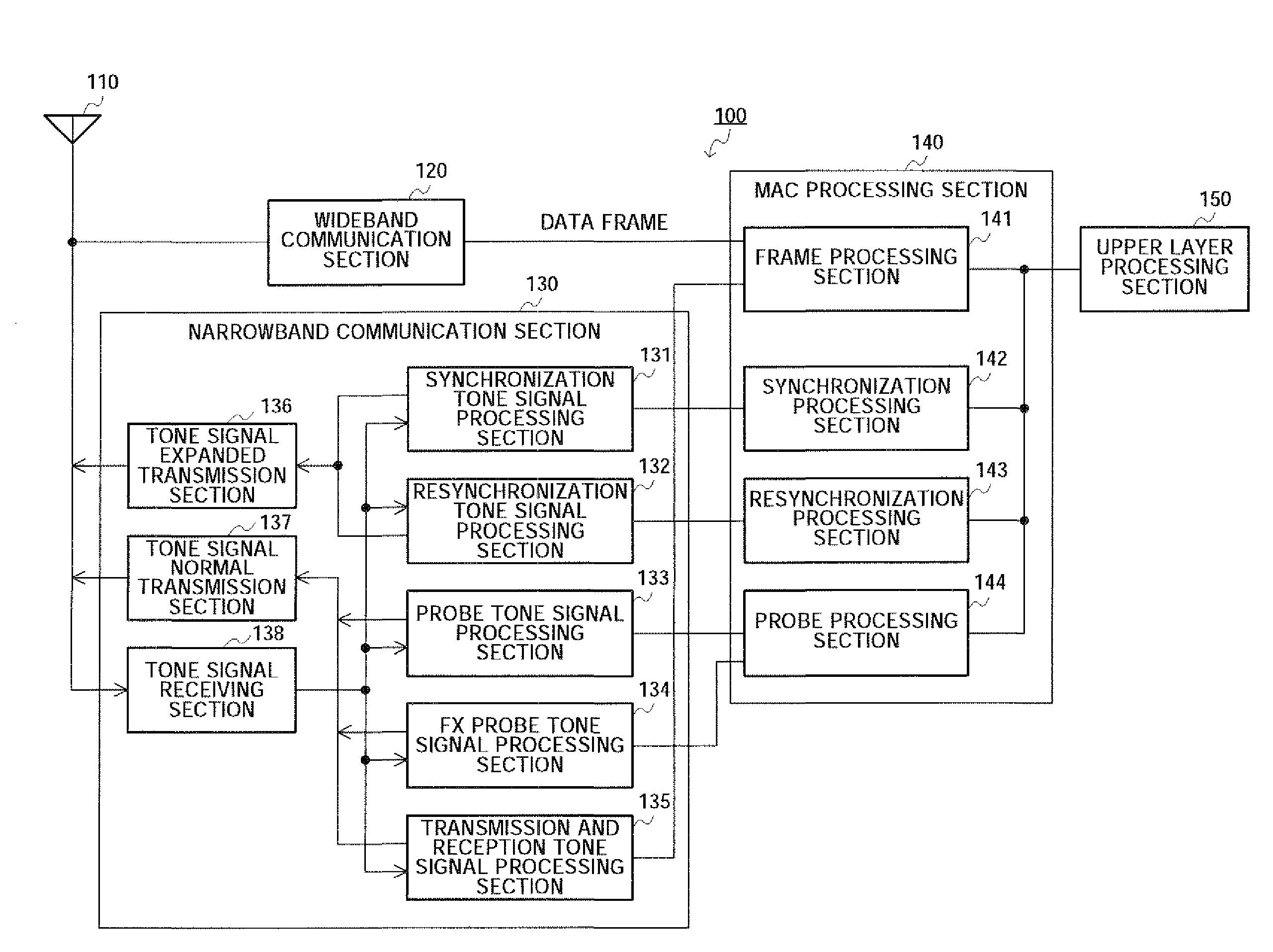
[0054]FIG. 3 is a block diagram showing a configuration of the wireless communication apparatus according to Embodiment 1 of the present invention.
[0055]Wireless communication apparatus (i.e. terminal) 100 shown in FIG. 3 has a file swapping application, and, roughly speaking, has antenna 110, wideband communication section 120, narrowband communication section 130, MAC processing section 140 and upper layer processing section 150. Here, as equipment building in wireless communication apparatus 100, for example, there are mobile terminals, notebook computers, mobile telephones, game machines and mobile players that have file swapping applications.
[0056]Antenna 110 is formed with, for example, a plurality of directional antennas covering each sector. The communication range is determined by controlling each directional antenna forming antenna 110 by a directivity controlling section (not shown).
[0057]Wideband communication section 120 transmits and receives millimeter wave UWE signal...
embodiment 2
[0120]A case will be described with Embodiment 2 where the tone signal synchronization scheme and a beacon period is combined. To be more specific, Embodiment 2 refers to a case where Embodiment 1 is realized and further the beacon period is implemented and a data communication time slot is assigned in the superframe using a beacon.
[0121]FIG. 12 is a block diagram showing a configuration of the wireless communication apparatus according to Embodiment 2 of the present invention. Further, this wireless communication apparatus has the same basic configuration as the corresponding wireless communication apparatus in Embodiment 1 shown in FIG. 3, and the same components will be assigned the same reference numerals and description thereof will be omitted.
[0122]Wireless communication apparatus 200 shown in FIG. 12 has a function of combining the tone signal synchronization scheme and the beacon period as described above and assigning data communication time slots in a superframe using beac...
embodiment 3
[0157]FIG. 23 is a block diagram showing a configuration of the wireless communication apparatus (hereinafter, “access point”) according to Embodiment 3 of the present invention. FIG. 24 is a block diagram showing a configuration of the wireless communication apparatus (hereinafter, “mobile terminal”) according to Embodiment 3 of the present invention.
[0158]
[0159]The present invention focuses upon the synchronization scheme carried out between above access point 1000 and mobile terminal 1100. The present embodiment proposes a scheme of acquiring communication synchronization between mobile terminal 1100 and access point 1000 according to a scheme similar to the synchronization scheme carried out by autonomous distribution. By acquiring synchronization by a tone signal between access point 1000 that transmits information and mobile terminal 1100 that receives information, only during the time slot in which access point 1000 transmits the tone signal, mobile terminal 1100 enters tone ...
PUM
 Abstract
Description
Claims
Application Information
 - Generate Ideas
- Intellectual Property
- Life Sciences
- Materials
- Tech Scout
- Unparalleled Data Quality
- Higher Quality Content
- 60% Fewer Hallucinations
Browse by: Latest US Patents, China's latest patents, Technical Efficacy Thesaurus, Application Domain, Technology Topic, Popular Technical Reports.
© 2025 PatSnap. All rights reserved.Legal|Privacy policy|Modern Slavery Act Transparency Statement|Sitemap|About US| Contact US: help@patsnap.com