

Phase comparator and regulation circuit
a phase comparator and circuit technology, applied in the direction of digital transmission, pulse automatic control, transmission, etc., can solve the problem of difficult use of phase difference detection in high-speed data communication
- Summary
- Abstract
- Description
- Claims
- Application Information
AI Technical Summary
Benefits of technology
Problems solved by technology
Method used
Image

Examples
first embodiment
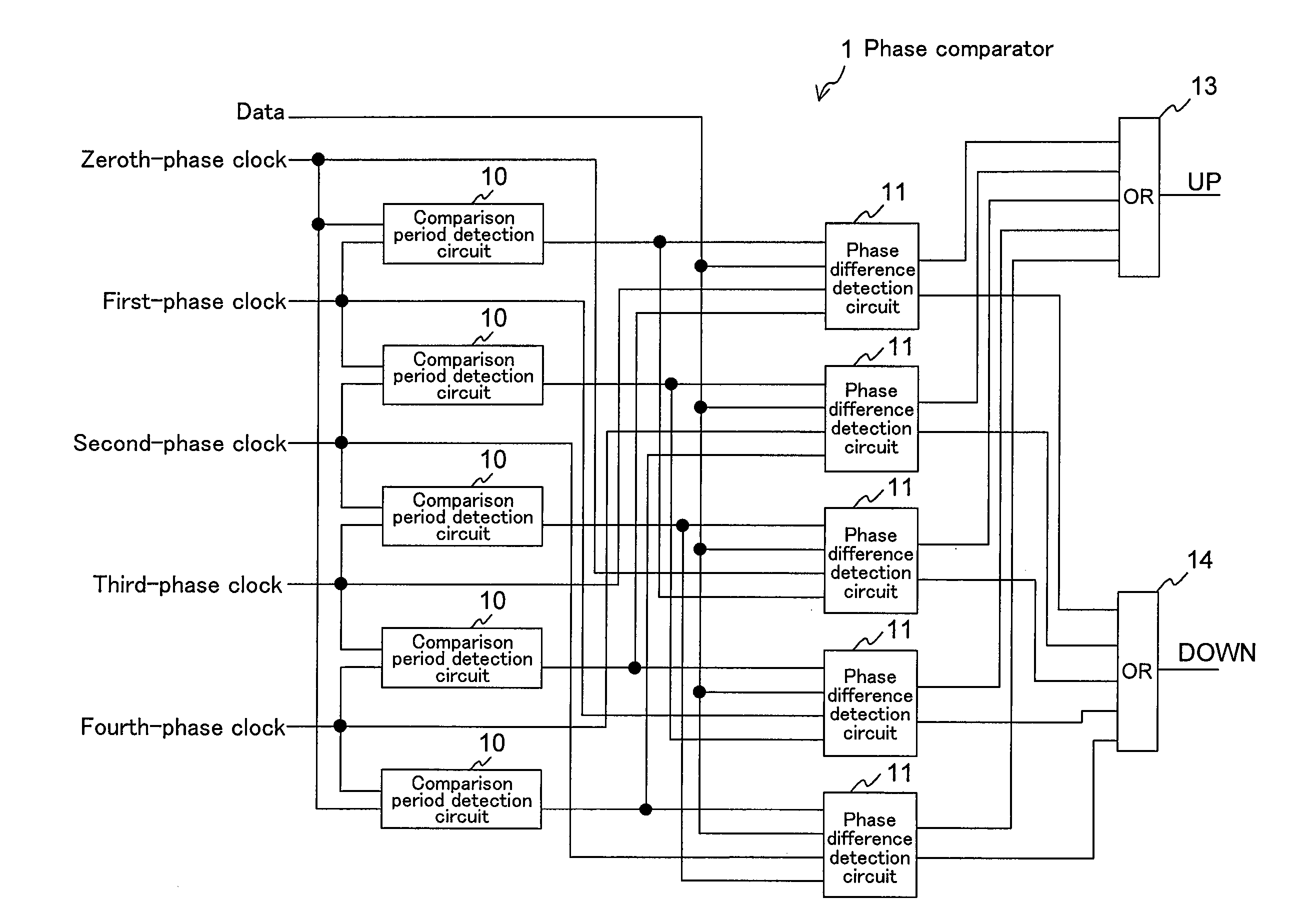
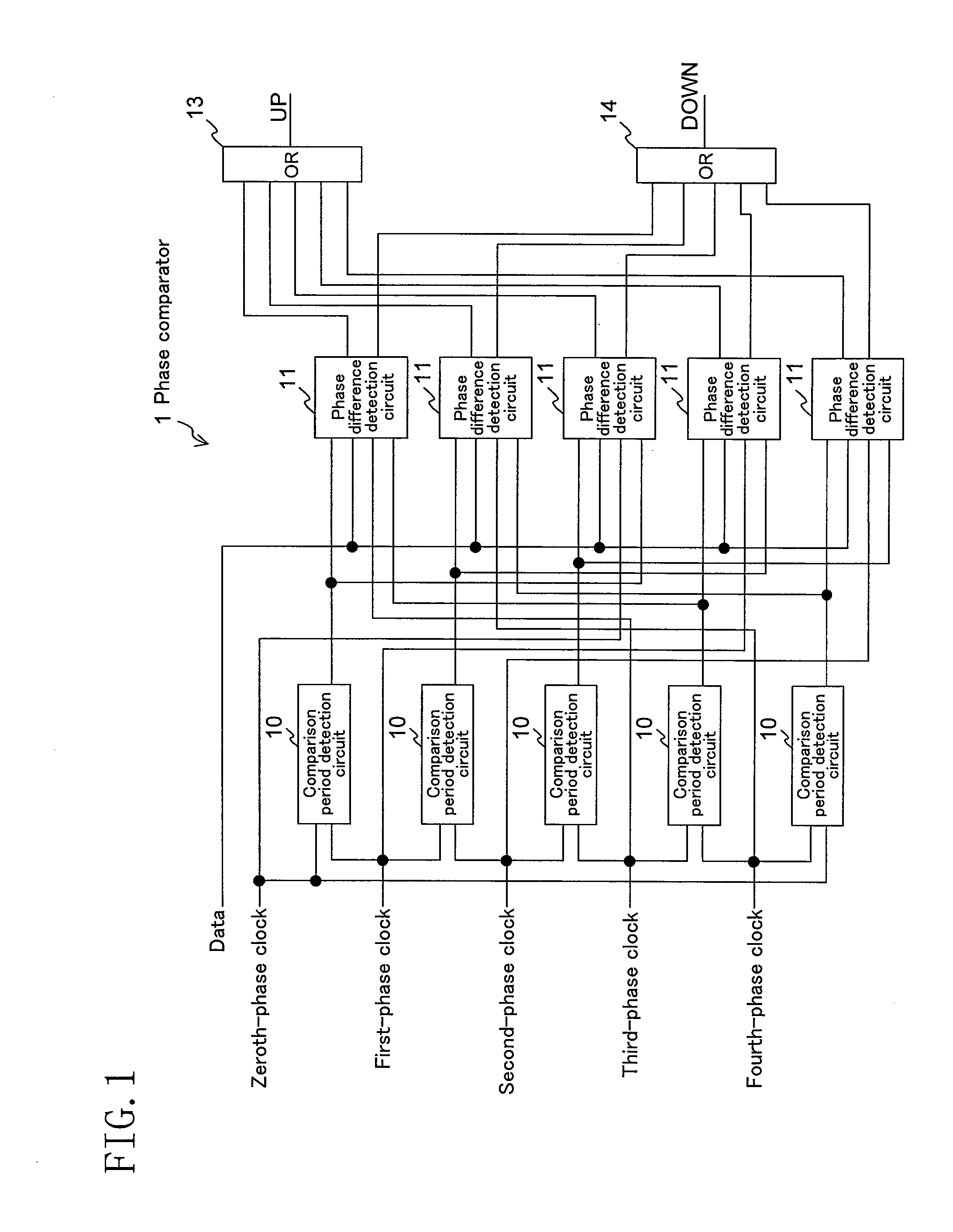
[0098]FIG. 1 shows a phase comparator according to a first embodiment of the present invention. The present embodiment corresponds to claims 1, 3 and 4.
[0099]In the figure, 1 denotes a phase comparator, 10 a comparison period detection circuit, 11 a phase difference detection circuit, 13 a first logical sum circuit, and 14 a second logical sum circuit.
[0100]Since the clock frequency is ⅕ of the data rate f (5=2N+1, N=2), there are five phases of clock signals, and the phase comparator 1 includes five (zeroth to fourth) each of the comparison period detection circuits (comparison period detection means) 10 and the phase difference detection circuits (phase difference detection means) 11.
[0101]The mth comparison period detection circuit 10 (m is an integer from 0 to 2N (=4) or less) receives the (m−1)th-phase clock signal as the first clock and the mth-clock signal as the second clock to output the mth comparison enable signal.
[0102]The mth phase difference detection circuit 11 receiv...
second embodiment
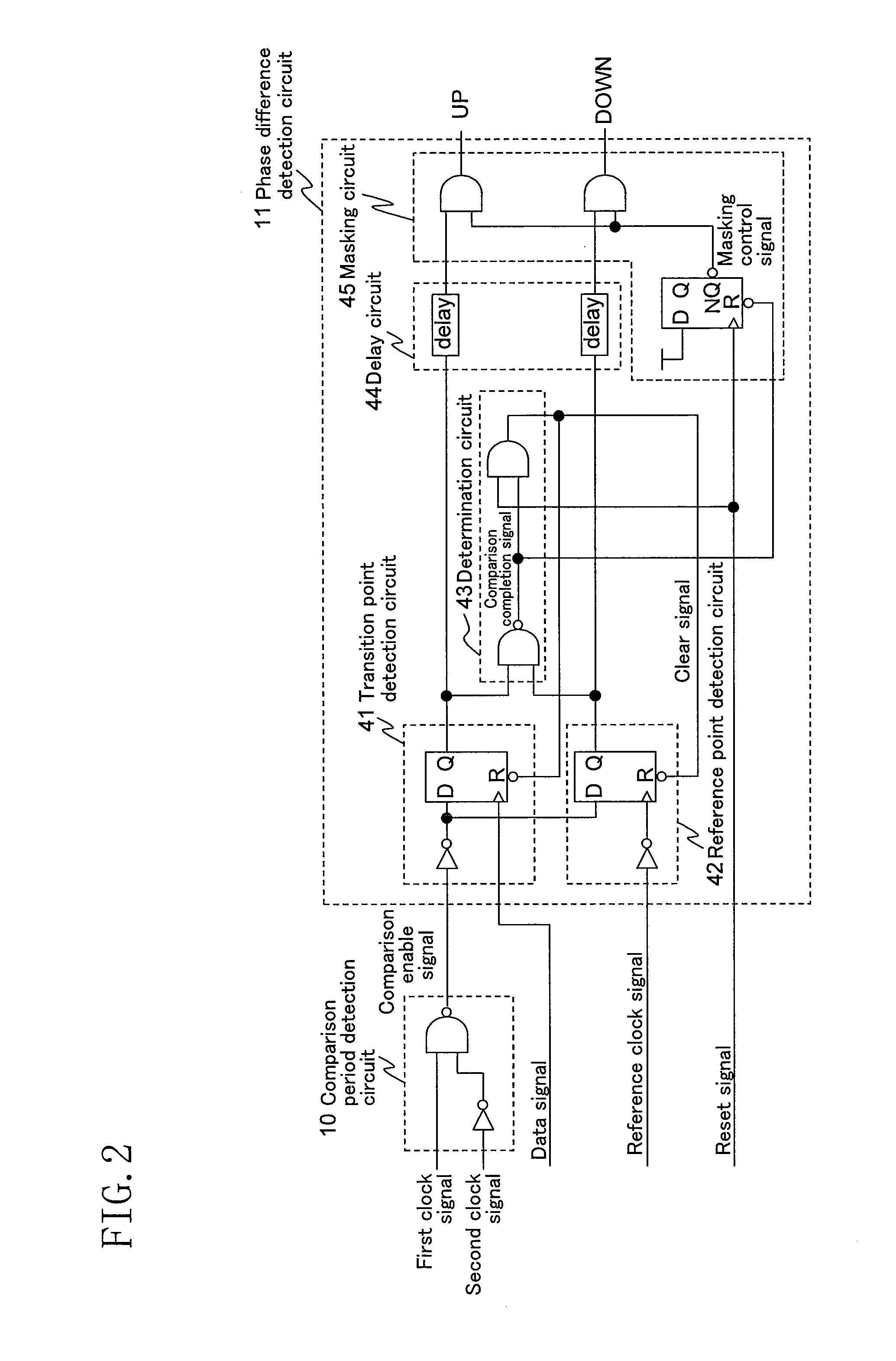
[0123]FIG. 4 shows the phase difference detection circuit 11 of a second embodiment for use in the phase comparator 1 shown in FIG. 1. The present embodiment corresponds to claim 5.
[0124]In the figure, 61 denotes a transition point detection circuit, 62 a reference point detection circuit, 63 a determination circuit, 64 a delay circuit, and 65 a masking circuit.
[0125]As in the first embodiment, the comparison period detection circuit 10 outputs L as the comparison enable signal during a period in which the first clock is H and the second clock is L, and outputs H during other periods.
[0126]The transition point detection circuit 61 is a flip flop circuit that holds H in synchronism with the rising edge of the data signal only during a period in which the comparison enable signal is L, keeps holding the value during a period in which the comparison enable signal is H, and turns the stored content to L when receiving the clear signal.
[0127]The transition point detection circuit 62 is a...
third embodiment
[0139]FIG. 6 shows a phase comparator according to a third embodiment of the present invention. The present embodiment corresponds to claims 6 and 7.
[0140]In the figure, 1 denotes a phase comparator, 10 a comparison period detection circuit, 11 a phase difference detection circuit, 12 a reset generation circuit, 13 a first logical sum circuit, and 14 a second logical sum circuit.
[0141]Since the clock frequency is ⅕ of the data rate f, there are five phases of clocks, and the phase comparator 1 includes five (zeroth to fourth) each of the comparison period detection circuits 10, the phase difference detection circuits 11, and the reset generation circuits 12.
[0142]The mth comparison period detection circuit 10 receives the (m−1)th-phase clock signal as the first clock, the mth-clock signal as the second clock, and the mth clear signal output from the mth phase difference detection circuit to output the mth comparison enable signal.
[0143]The mth reset generation circuit 12 receives th...
PUM
 Abstract
Description
Claims
Application Information