Abnormality Detection Device for Continuously Variable Transmission and Method of Detecting Abnormality of the Continuously Variable Transmission

Active Publication Date: 2015-07-23
SUBARU CORP
View PDF6 Cites 4 Cited by
  • Summary
  • Abstract
  • Description
  • Claims
  • Application Information

AI Technical Summary

Benefits of technology

[0016]The abnormality detection device for a continuously variable transmission may further include an output module that outputs the upper limit of torque to the engine control unit, and in the case where the upper limit of torque is determined to be abnormal by the determination module, the output module stops outputting of the upper limit of torque to the engine control unit.
[0017]Another aspect of the present disclosure provides a method of detecting abnormality of the continuously variable transmission including: setting an upper limit of torque based on an allowable input torque for the continuously variable transmission, the upper

Problems solved by technology

While, as described above, the engine output torque is limited in order to absorb the difference in responsiveness between the engine and the continuously variable transmission, the engine output torque is also limited, for example, in order to protect the continuously variable transmission (for example, to prevent the chain from sliding, to prevent the clutch from being damaged, and/or to prevent input of torque greater than or equal to an allowable torque).
Although it is extremely rare for such an electrical control device to have a failure, a fault might occur in the microcomputer, for example, a fault in a memory such as a RAM and a register (for example, written data and read data do not match), a fault in a logical operation circuit, and variation in clock signal might occur.
In addition, an error in setting or writing ROM data (such as control data) might occur.
If such a h

Method used


Image

  • Abnormality Detection Device for Continuously Variable Transmission and Method of Detecting Abnormality of the Continuously Variable Transmission
  • Abnormality Detection Device for Continuously Variable Transmission and Method of Detecting Abnormality of the Continuously Variable Transmission
  • Abnormality Detection Device for Continuously Variable Transmission and Method of Detecting Abnormality of the Continuously Variable Transmission

Examples


Embodiment Construction

[0020]Hereinafter, a preferred implementation of the present disclosure will be described in detail with reference to the accompanying drawings. It is to be noted that the same or corresponding components in the drawings will be denoted by the same symbol. Also, the same elements in the drawings are labeled with the same symbols and a redundant description will be omitted.

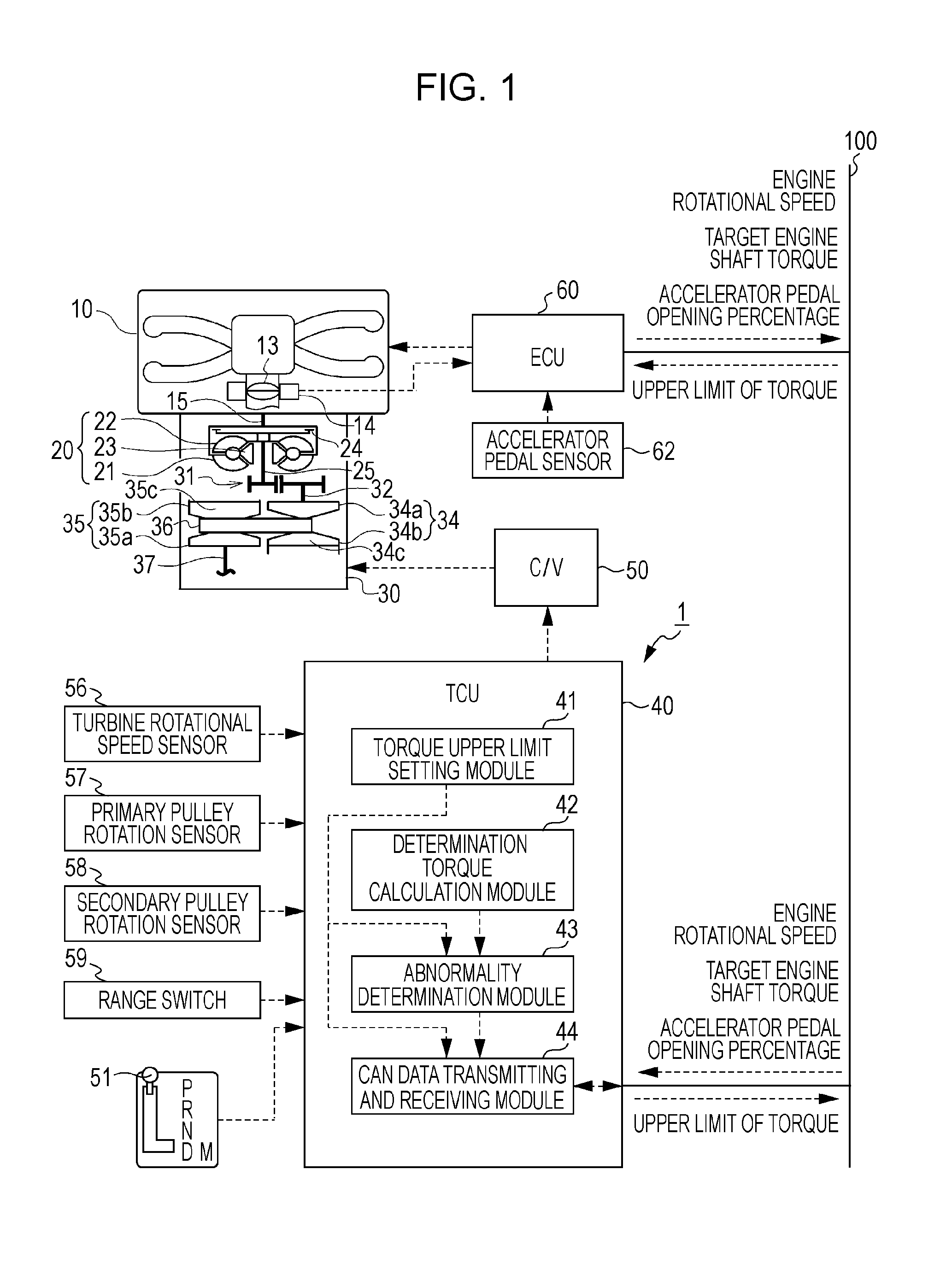
[0021]First, the configuration of an abnormality detection device 1 for a continuously variable transmission according to the implementation will be described with reference to FIG. 1. FIG. 1 is a block diagram illustrating the configuration of the abnormality detection device 1 for a continuously variable transmission and a continuously variable transmission 30 to which the abnormality detection device 1 is applied.

[0022]An engine 10 may be of any type and the present implementation employs a horizontally-opposed four-cylinder direct-injection gasoline engine. In the engine 10, air sucked by an air cleaner (not il...


PUM


Abstract

An abnormality detection device includes: a torque upper limit setting module that sets an upper limit of torque based on an allowable input torque for the continuously variable transmission, the upper limit of torque limiting an output torque of an engine; a determination torque calculation module that determines an acceleration requested by a driver based on an amount of operation of an accelerator, obtains a running resistance of a vehicle according to the requested acceleration, and calculates a determination torque for determining abnormality of the upper limit of torque based on the running resistance of the vehicle and a gear ratio of the continuously variable transmission; and an abnormality determination module that determines the upper limit of torque to be abnormal in the case where the upper limit of torque is less than or equal to the determination torque.

Description

CROSS-REFERENCE TO RELATED APPLICATIONS[0001]The present application claims priority from Japanese Patent Application No. 2014-010011 filed on Jan. 23, 2014, the entire contents of which are hereby incorporated by reference.BACKGROUND[0002]1. Technical Field[0003]The present disclosure relates to an abnormality detection device for a continuously variable transmission and a method of detecting abnormality of the continuously variable transmission.[0004]2. Related Art[0005]These days, continuously variable transmissions (CVT) such as a chain-type CVT or a belt-type CVT, which allow a gear ratio to be continuously changed, are widely in practical use (see, for example, Japanese Unexamined Patent Application Publication (JP-A) No. 2001-225672). In the continuously variable transmission described in JP-A No. 2001-225672, in order to suppress the degradation of power characteristics and a sense of discomfort due to a difference in responsiveness between the engine and the continuously va...

Claims


Application Information

Patent Timeline
IPC IPC(8): F16H61/12B60W10/06B60W10/101F16H61/66
CPCF16H61/12F16H61/66F16H2061/6611B60W10/101F16H2061/1268B60W10/06B60W50/038B60W50/04F16H61/662B60W2050/022B60W2510/0657B60W2510/1005B60W2510/1015B60W2510/104B60W2520/10B60W2520/105B60W2530/16B60W2540/10B60Y2400/72
Inventor KINOSHITA, TAKAHIRO
Owner SUBARU CORP
Why Eureka
Try Eureka