
Method for producing a metal tube by clad rolling one more profiles to form at least one channel, a clad rolling mill for joining one or more profiles, a clad rolled metal tube

a metal tube and clad rolling technology, which is applied in the direction of envelopes/bags making machinery, paper/cardboard containers, lighting and heating apparatus, etc., can solve the problems of slow and expensive process of soldering, difficult manufacturing, etc., and achieve the effect of efficient production of metal tubes

Inactive Publication Date: 2009-10-22
LUVATA ESPOO OY
View PDF33 Cites 7 Cited by
  • Summary
  • Abstract
  • Description
  • Claims
  • Application Information

AI Technical Summary

Benefits of technology

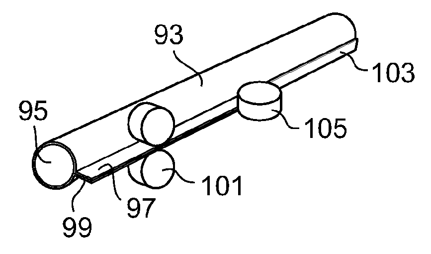
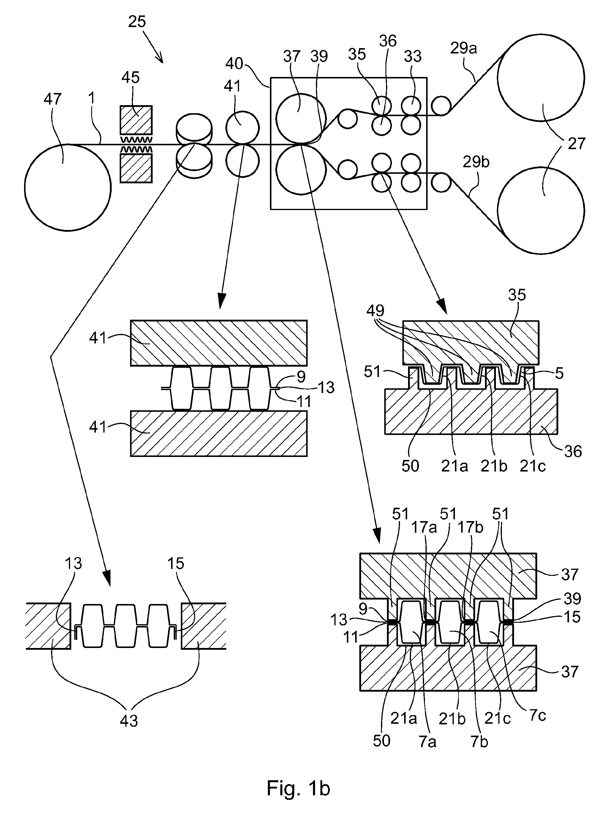
[0007]By producing the metal tube, having at least one channel by clad-rolling at least a first and a second portion of at least one metal profile to each other, so that a seal is formed, which both seals the channel and holds the one or more metal profiles together, an efficient production of the metal tube is achieved. Clad-rolling can be efficient in many ways. Clad-rolling can be performed at great speed, and thus the productivity of the metal tube production is high. Clad-rolling is also simple to use even for hard metals, such as copper, which is a preferred material for metal tubes for use in heat exchangers. Furthermore cladrolling is relatively inexpensive and the equipment needed for clad-rolling is also relatively inexpensive. Clad-rolling may be a cold process, in difference to for example extrusion or soldering, which means that the characteristics of the material may be more easily controlled. Furthermore, no additional internal structure is needed, either for support or in order to form channels.
[0023]In one embodiment the metal profile or profiles is heated before the winding of the tube onto a storage reel. The elevated temperature make the material of the tube more ductile, allowing easier winding of the rube with less risk for introducing cracks or damages to the tube.

Problems solved by technology

One problem with multi-channel tubes is that they are difficult to manufacture.
Soldering however is a slow and expensive process.

Method used


Image

  • Method for producing a metal tube by clad rolling one more profiles to form at least one channel, a clad rolling mill for joining one or more profiles, a clad rolled metal tube
  • Method for producing a metal tube by clad rolling one more profiles to form at least one channel, a clad rolling mill for joining one or more profiles, a clad rolled metal tube
  • Method for producing a metal tube by clad rolling one more profiles to form at least one channel, a clad rolling mill for joining one or more profiles, a clad rolled metal tube

Examples


Embodiment Construction

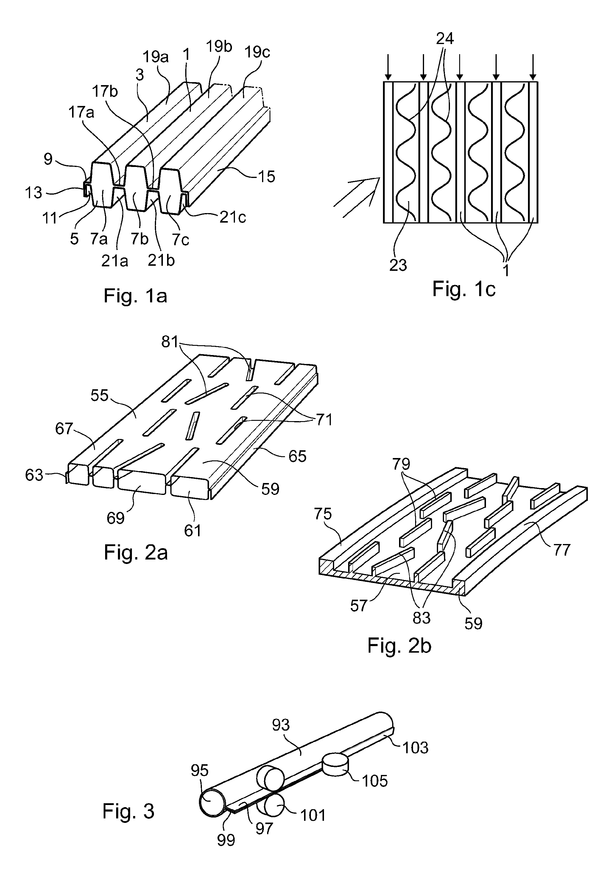
[0030]In FIG. 1a a metal tube 1 according to one embodiment of the invention is shown. The metal tube 1 comprises a first metal profile 3 and a second metal profile 5. The first 3 and the second metal profiles 5 are arranged to form at least one channel for conduction of a fluid. In this example the metal profiles 3, 5 are adapted to form three channels 7a, 7b, 7c for conduction of a fluid. The channels 7a-c are arranged in parallel with each other and extend along the length of the metal profiles. Thus the metal tube comprises long channels for conduction of the fluid. If a shorter tube is needed the tube may be cut. In this example the channels are adapted to conduct the same fluid and with the same direction of flow, but in another example the channels may conduct different fluids. In this example the metal tube 1 consists of two metal profiles only. In another example the metal tube may comprise two or more metal profiles. Similarly, the metal tube may comprise three or more cha...


PUM

PropertyMeasurementUnit
Temperatureaaaaaaaaaa
Fractionaaaaaaaaaa
Lengthaaaaaaaaaa

Abstract

A method for producing a metal tube including arranging at least one metal profile to form at least one channel for conduction of a fluid. The at least one metal profiled is fed into a clad-rolling mill. A first and second portion of the at least one metal profile are clad-rolled to each other, so that the first and the second portions are joined with each other. The first and the second portions form a seal that holds the at least one metal profile together and seals at least part of the channel. A clad-rolling mill is adapted to produce a metal tube and a metal tube.

Description

FIELD OF THE INVENTION[0001]The present invention relates to a metal tube for conduction of a fluid, a method for producing a metal tube, and a clad-rolling mill.TECHNICAL FIELD[0002]Metal tubes are used to conduct fluids in various applications. In one application tubes are used to allow an exchange of heat between two fluids. This is useful for example in heat exchangers and heat pumps such as air conditioners. In one application one fluid is conducted inside the metal tube, while another fluid surrounds the tube. In order to ensure an efficient heat transfer and to lower the fall of pressure for the surrounding fluid when it flows across the tubes, such a metal tube is preferably substantially flat. Thus a large surface area for heat conduction is also established.[0003]In order for a heat pump to have a high performance high pressures are needed to achieve an efficient heat pump cycle. Throughout the heat pump cycle the fluid changes its state between being a liquid and a gas or...

Claims


Application Information

Patent Timeline
IPC IPC(8): B32B1/08B23K20/04
CPCB21C37/102B21C37/151B21D53/04B23K20/04B23K2201/045B23K2201/06Y10T428/13F28D1/0308F28D9/0031F28F3/042F28F3/048F28F2225/04B23K2201/14B23K2101/045B23K2101/06B23K2101/14
Inventor IRWIN, MARKKEIFE, HANS
Owner LUVATA ESPOO OY
Learn More