Ultrasonic shears stop pad

a technology of stop pad and ultrasonic shear, which is applied in the field of ultrasonic devices, can solve the problems of requiring the pad material to be optimized for tissue contact and frictional effects, and achieve the effect of reducing negative frictional effects

Inactive Publication Date: 2009-10-22
ETHICON ENDO SURGERY INC
View PDF0 Cites 213 Cited by
  • Summary
  • Abstract
  • Description
  • Claims
  • Application Information

AI Technical Summary

Benefits of technology

[0006]The present invention comprises a stop pad connected to clamping arm and separate from the tissue pad. Said stop pad contacts the ultrasonic surgical blade but does not engage tissue and may be optimized through material selection, geometry, and position to reduce negative frictional effects independent of tissue pad.
[0010]Several benefits and advantages are obtained from one or more of the embodiments of the invention. Having a stop pad not in contact with tissue allows material to be chosen with a different hardness, stiffness, lubricity, dynamic coefficient of friction, heat transfer coefficient, abradability, heat deflection temperature, and / or melt temperature to improve the wearability of the tissue pad which is important when high clamping forces are employed because tissue pads wear faster at higher clamping forces than at lower clamping forces. Furthermore, the stop pad surface need not be parallel or conformal to the blade surface at the point of contact. Applicants found that by through proper material selection, geometry, and position of the stop pad, tissue pad wearability is improved. Furthermore, vessel coaptation and transaction can be optimized by proper material selection, geometry, and position of the stop pad independent of the material selection, geometry, and position of the tissue pad.

Problems solved by technology

However, this method has the limitation of requiring the pad material to be optimized for tissue contact and for frictional effects.

Method used


Image

  • Ultrasonic shears stop pad
  • Ultrasonic shears stop pad
  • Ultrasonic shears stop pad

Examples


Embodiment Construction

[0019]Before explaining the present invention in detail, it should be noted that the invention is not limited in its application or use to the details of construction and arrangement of parts illustrated in the accompanying drawings and description. The illustrative embodiments of the invention may be implemented or incorporated in other embodiments, variations and modifications, and may be practiced or carried out in various ways. Furthermore, unless otherwise indicated, the terms and expressions employed herein have been chosen for the purpose of describing the illustrative embodiments of the present invention for the convenience of the reader and are not for the purpose of limiting the invention.

[0020]It is understood that any one or more of the following-described embodiments, examples, etc. can be combined with any one or more of the other following-described embodiments, examples, etc.

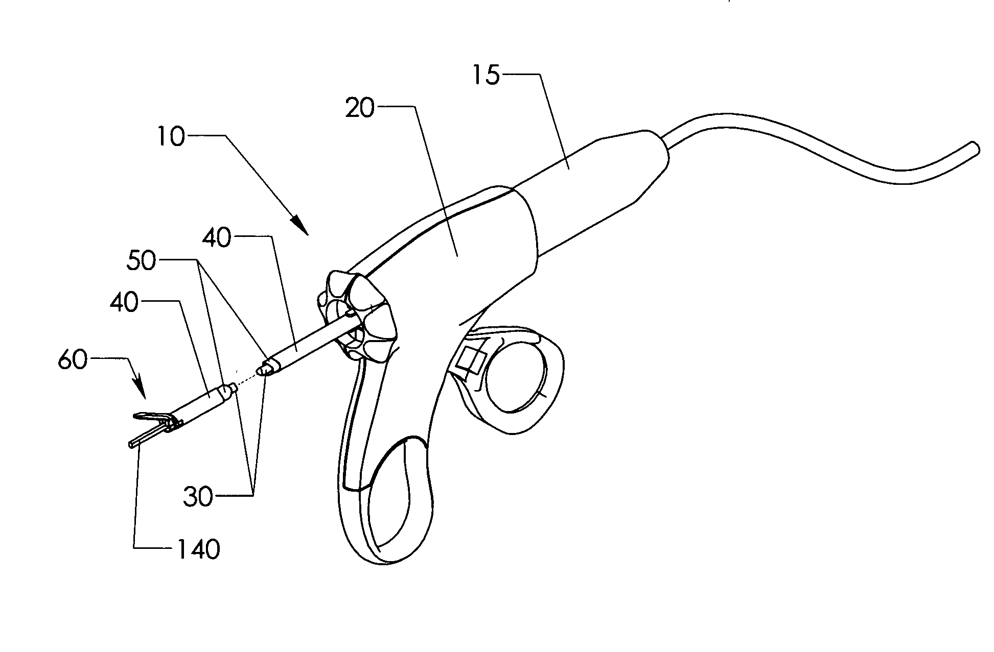
[0021]Referring now to the Figures, in which like numerals indicate like elements, FIG. 1 ill...


PUM


Abstract

An ultrasonic-surgical-shears stop pad has a stop-pad body including a base material and at least one filler material. An alternate ultrasonic-surgical-shears stop pad has a stop-pad body adjacent to tissue pad. An ultrasonic surgical shears includes an ultrasonic surgical blade and a clamping arm which is operable to open and close toward the blade and which has a transversely and resiliently flexible distal tip. An alternate ultrasonic surgical shears includes an ultrasonic surgical blade, a clamping arm operable to open and close toward the blade, and a stop pad attached to the clamping arm and having a blade contact surface, wherein at least a portion of the stop pad is resiliently flexible in a direction substantially perpendicular to the blade contact surface.

Description

[0001]This application hereby claims the priority of U.S. Provisional Application 61 / 124,643 filed on Apr. 18, 2008. U.S. Provisional Application 61 / 124,643 is incorporated by reference.FIELD OF THE INVENTION[0002]The present invention relates, in general, to ultrasonic devices and, more particularly, to methods and devices that provide ultrasonic shears with improved cutting and hemostasis.BACKGROUND OF THE INVENTION[0003]Ultrasonic surgical instruments are known which include an ultrasonic surgical shears having an ultrasonic surgical blade, a clamping arm operable to open and close toward the blade, and a polytetrafluoroethylene tissue pad which is attached to the clamping arm and which includes a clamping surface. The clamping arm exerts a clamping force on a blood vessel which is positioned between the clamping surface of the tissue pad and the blade. The result of the ultrasonically-vibrating ultrasonic surgical blade and the clamping force on the blood vessel is a coaptation ...

Claims


Application Information

Patent Timeline
Patent Type & Authority Applications(United States)
IPC IPC(8): A61B17/3201
CPCA61B2017/320076A61B17/320092A61B2017/320078A61B2017/320094
Inventor BEAUPRE, JEAN MICHAEL
Owner ETHICON ENDO SURGERY INC
Why Eureka
Try Eureka