Method of and apparatus for manufacturing a tire bead

a manufacturing method and tire bead technology, applied in the field of tire bead manufacturing methods and apparatuses, can solve the problems of increased overlap, difficult butt and jointing of filler rubber, and increased manufacturing costs, so as to improve the manufacturing efficiency of tire beads

Active Publication Date: 2009-10-29
TOYO TIRE & RUBBER CO LTD
View PDF8 Cites 32 Cited by
  • Summary
  • Abstract
  • Description
  • Claims
  • Application Information

AI Technical Summary

Benefits of technology

[0025]As described above, with the method of and the apparatus for manufacturing a tire bead, according to the invention, a filler rubber, which is extrusion-molded to be triangular-shaped in cross section, can be held in an upright posture on an outer peripheral surface of a bead core to be stuck thereto, and end surfaces of ...

Problems solved by technology

Therefore, unless a butting method, in which a configuration of the leading end F1 being made oblique is taken into consideration, is adopted, it is difficult to butt and join the filler rubber F in a state of being held in an upright posture to the outer peripheral surface of the bead core C and if the filler rubber is temporarily joined, crack is liable to generate on an outer edge side of a joined portion J.
In particular, in the case where the filler rubber is lengthened on an outer edge side to ensure a sufficient, circumferential length, there is caused a problem that overlap is increas...

Method used


Image

  • Method of and apparatus for manufacturing a tire bead
  • Method of and apparatus for manufacturing a tire bead
  • Method of and apparatus for manufacturing a tire bead

Examples


Embodiment Construction

[0026]A mode for carrying out the invention will be described below on the basis of an embodiment shown in the drawings.

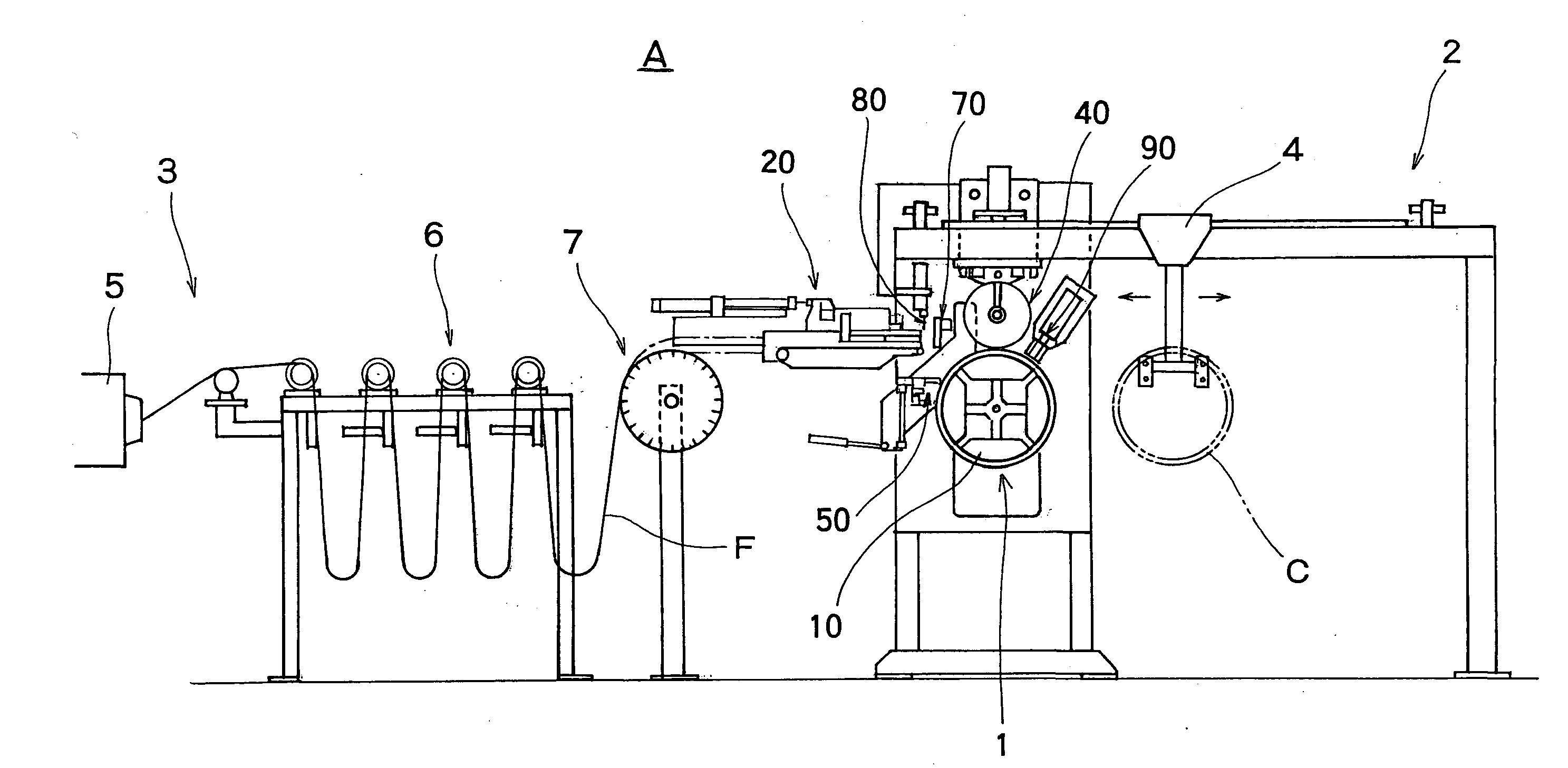
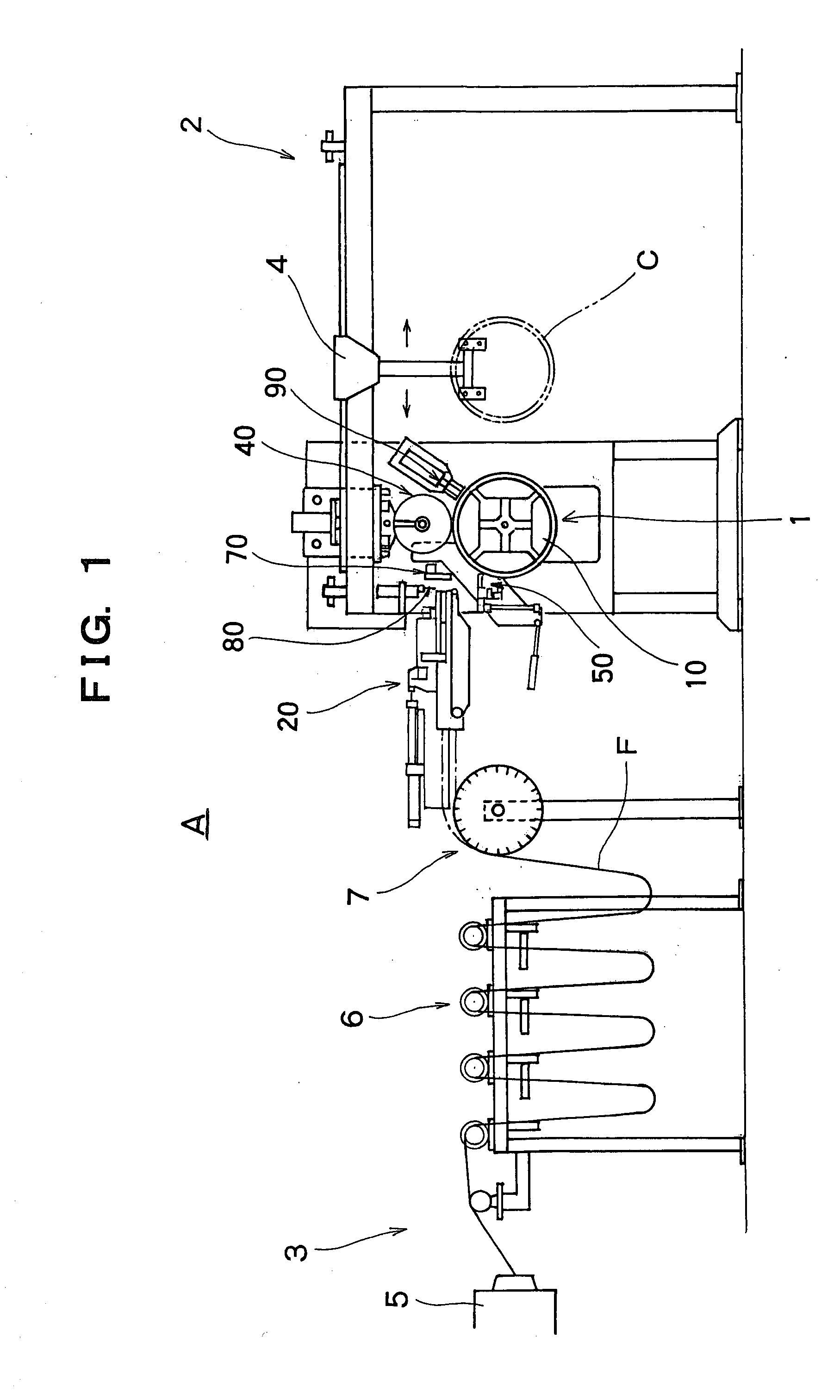
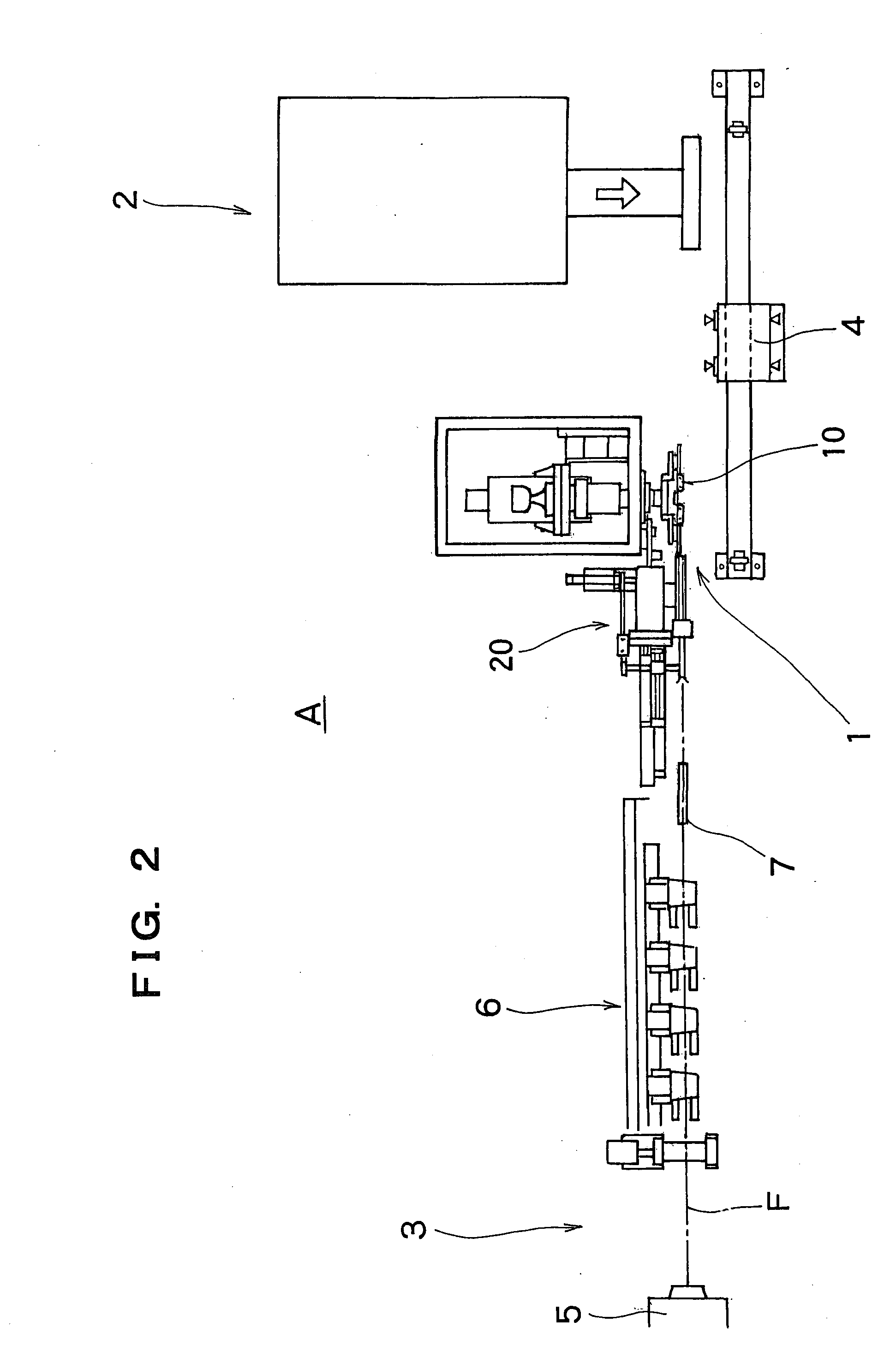
[0027]FIG. 1 is a schematic, front view showing a bead manufacturing apparatus of the invention, FIG. 2 is a schematic, plan view showing the bead manufacturing apparatus, FIG. 3 is a schematic, front view showing a sticking device about a rotary support body, and FIG. 4 is a longitudinal, cross sectional view showing the rotary support body. FIG. 5 is a front view showing a feeding device of a filler rubber as viewed from laterally of a feeding direction, FIG. 6 is a plan view showing the feeding device, and FIGS. 7 and 8 are cross sectional views taken along the line VII-VII and the line VIII-VIII in FIG. 6, respectively. FIG. 9 is a side view showing a pressing roller, and FIG. 10 is a view illustrating, in enlarged scale, a state, in which the filler rubber is pressed. FIG. 11 is a front view illustrating a state, in which first interposing means and second int...


PUM

PropertyMeasurementUnit
Angleaaaaaaaaaa
Lengthaaaaaaaaaa
Angleaaaaaaaaaa

Abstract

A filler rubber being triangular-shaped in cross section can be held in an upright posture to be stuck to an outer peripheral surface of a bead core and a leading end and a trailing end can be butted against each other to be joined without the generation of crack. A filler rubber (F) is held in an upright posture to be wound around an outer peripheral surface of a bead core (C) supported by a rotary support body (10), and in joining a leading end (F1) and a trailing end (F2) of the filler rubber cut to a predetermined length, the neighborhood of the leading end and the neighborhood of the trailing end, respectively, are interposed by first and second interposing means (50), (70), and one (50) of the interposing means is displaced toward the other from a state, in which the leading end (F1) and the trailing end (F2) are opposed to each other whereby end surfaces of the leading end (F1) and the trailing end (F2) are butted against each other.

Description

TECHNICAL FIELD OF THE INVENTION[0001]The present invention relates to a method of and an apparatus for manufacturing a tire bead having a filler rubber stuck to an outer peripheral surface of a bead core.BACKGROUND ART[0002]A tire is formed by combining a plurality of rubber members and a plurality of reinforcement members made mainly of steel or synthetic fiber cord, and bead portions as assembled to a rim are formed on both inner peripheral portions of a tire.[0003]Embedded in the bead portion is a tire bead formed by sticking a band-shaped rubber member (referred to as filler rubber in the invention), which is triangular-shaped (mainly, longitudinally triangular-shaped in cross section) in cross section and referred to as bead filler or the like, to a diametrically, outer peripheral surface of a bead core formed by winding mainly a steel wire in a circular-ring shaped configuration.[0004]Conventionally, while the tire bead B is manufactured by sticking a filler rubber F, which i...

Claims


Application Information

Patent Timeline
IPC IPC(8): B29D30/48
CPCB29D2030/482B29D30/48
Inventor MATSUYAMA, TOSHIYATANAKA, TOSHIYUKI
Owner TOYO TIRE & RUBBER CO LTD
Why Eureka
Try Eureka