Imaging Device and Camera Body

a technology which is applied in the field of imaging device and camera body, can solve the problems of affecting the accuracy of distortion correction, the amount of information used for distortion correction is far larger, and the distortion of the optical image formed by the optical system is sometimes distorted by distortion, etc., and achieves the effect of enhancing convenience and accuracy of distortion correction

Active Publication Date: 2009-10-29
PANASONIC CORP
View PDF12 Cites 37 Cited by
  • Summary
  • Abstract
  • Description
  • Claims
  • Application Information

AI Technical Summary

Benefits of technology

[0012]It is an object to provide an imaging device with which good distortion correction accuracy is ensured, and convenience is enhanced.
[0014]With this imaging device, the first correction information held in the first holding part of the interchangeable lens unit is brought into the camera body by the correction information acquisition part. An interpolation operation or an extrapolation operation is performed on this first correction information, and second correction information is produced by the operation part. Since the correction of distortion is performed on the basis of this second correction information, even if there is only a small amount of first correction information, enough information to ensure accurate distortion correction by the interpolation operation or the extrapolation operation can be acquired as second correction information. Consequently, with this imaging device, distortion correction accuracy can be ensured while also enhancing convenience.
[0024]With this camera body, first correction information is brought from the interchangeable lens unit into the camera body by the correction information acquisition part. This first correction information is subjected to an interpolation operation or an extrapolation operation, and second correction information is produced by the operation part. Since distortion is corrected on the basis of this second correction information, even if there is only a small amount of first correction information, enough information to ensure accurate distortion correction by the interpolation operation or the extrapolation operation can be acquired as second correction information. Consequently, with this camera body, distortion correction accuracy can be ensured while also enhancing convenience.

Problems solved by technology

However, the optical image formed by the optical system is sometimes distorted by distortion.
Accordingly, the subject may be distorted in the image when the acquired image data is displayed as an image, and this is undesirable.
However, the amount of information used for correcting distortion is far larger than the amount of other information transmitted from the interchangeable lens to the camera body, so data transmission can be expected to take a long time.
If transmission takes more time, then the start-up of the imaging device will also take longer, which is extremely inconvenient to the user.
It is possible to reduce the amount of correction information, but this is undesirable because it reduces the accuracy of distortion correction.

Method used


Image

  • Imaging Device and Camera Body
  • Imaging Device and Camera Body
  • Imaging Device and Camera Body

Examples


first embodiment

[0047]Summary of Digital Camera

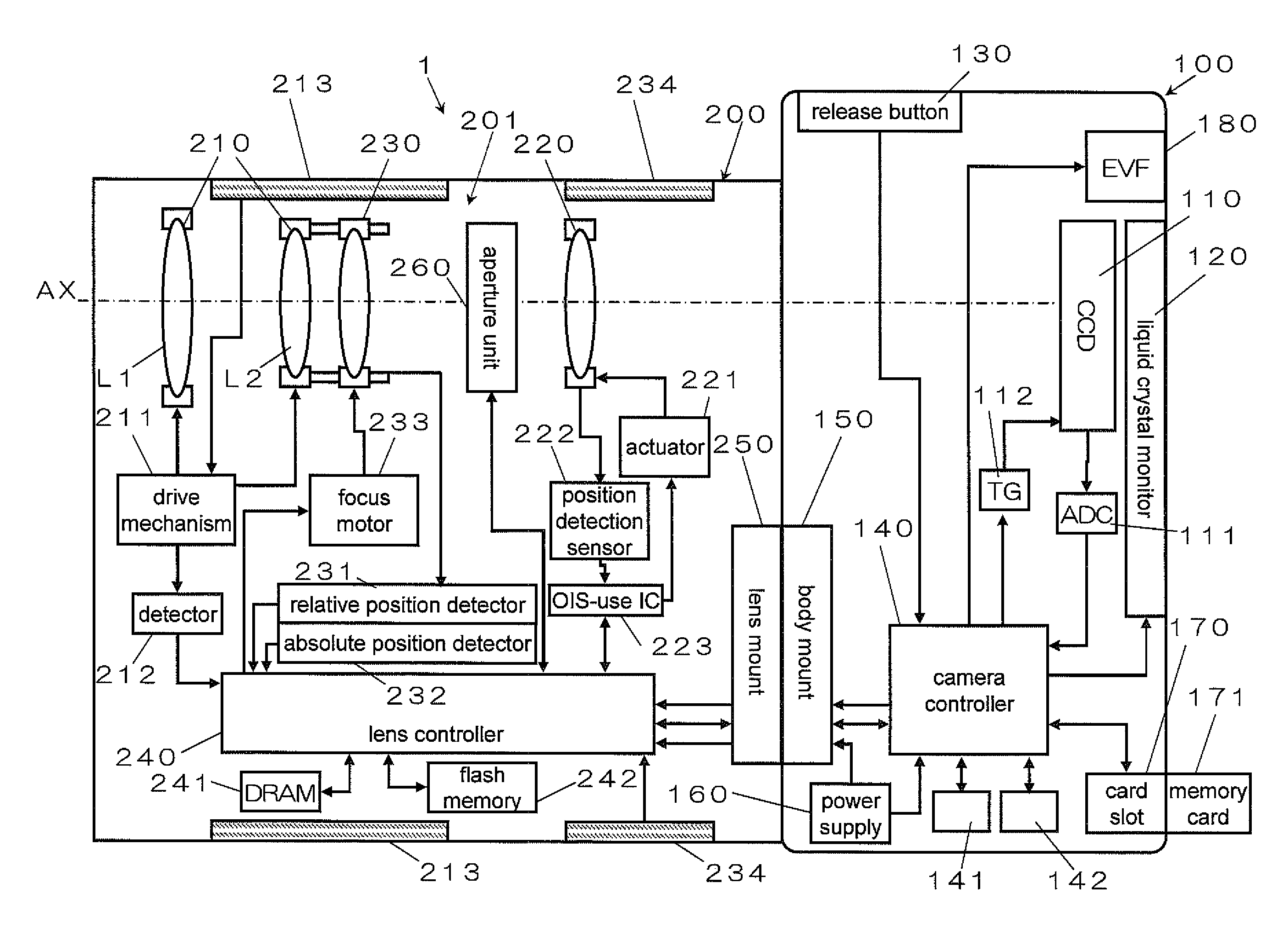
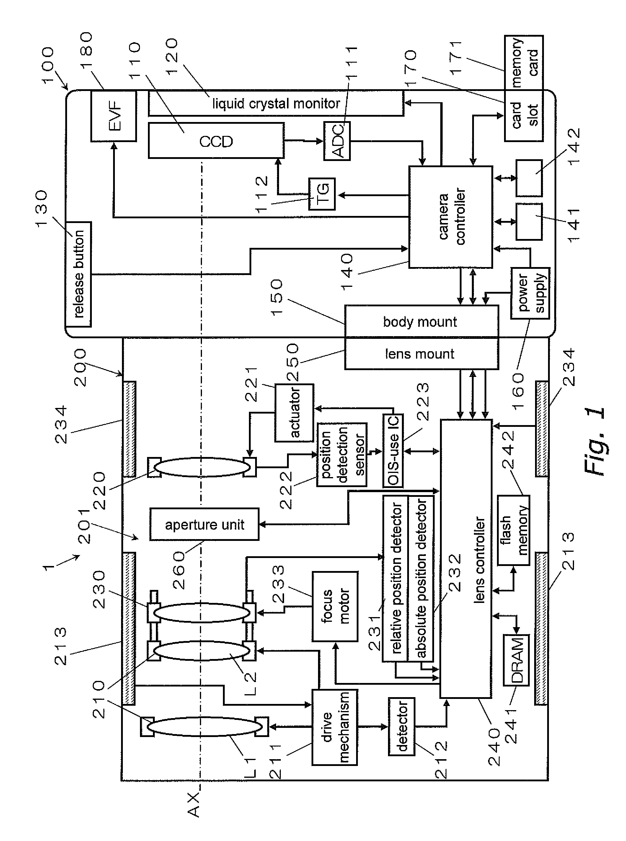
[0048]FIG. 1 is a block diagram of the configuration of a digital camera 1 pertaining to a first embodiment. The digital camera 1 (an example of the imaging device) is a digital single lens reflex camera with an interchangeable lens. More specifically, as shown in FIG. 1, the digital camera 1 comprises a camera body 100 and an interchangeable lens unit 200 that can be attached to or removed from the camera body 100. The digital camera 1 is, for example, able to capture still and moving pictures.

[0049]The digital camera 1 has a function of electrically correcting distortion produced by the optical system. This distortion correction will be discussed below.

[0050]Configuration of Camera Body

[0051]As shown in FIG. 1, the camera body 100 mainly comprises a CCD image sensor 110 (an example of the image acquisition part), a liquid crystal monitor 120, an electronic viewfinder 180, a camera controller 140, a body mount 150, a power supply 160, and a card slot ...


PUM


Abstract

A digital camera comprises an interchangeable lens unit and a camera body. The interchangeable lens unit is provided to form an optical image of a subject. A flash memory is configured to hold a correction coefficient table used to electrically correct distortion produced by the optical system. The camera body has a CCD image sensor, a correction coefficient acquisition part, an operation part, and a correction processor. The correction coefficient acquisition part is configured to acquire the correction coefficient table held in the flash memory. The operation part is configured to produce correction data by performing an interpolation operation or an extrapolation operation on the information obtained from the correction coefficient table. The correction processor is configured to correct distortion in the image data on the basis of information produced by the operation part.

Description

CROSS-REFERENCE TO RELATED APPLICATIONS[0001]This application claims priority to Japanese Patent Application No. 2008-116744 filed on Apr. 28, 2008. The entire disclosure of Japanese Patent Application No. 2008-116744 is hereby incorporated herein by reference.BACKGROUND[0002]1. Technical Field[0003]The technical field relates to an imaging device and a camera body, and more particularly to an imaging device with an interchangeable lens, and a camera body to which an interchangeable lens unit is mounted.[0004]2. Description of the Related Art[0005]A digital camera is a known example of an imaging device that acquires image data of a subject. A digital camera has an optical system for forming an optical image of the subject, and an imaging element configured to convert the optical image into image data. This allows image data of the subject to be acquired.[0006]However, the optical image formed by the optical system is sometimes distorted by distortion. Accordingly, the subject may b...

Claims


Application Information

Patent Timeline
Patent Type & Authority Applications(United States)
IPC IPC(8): G03B13/00H04N5/225
CPCG03B13/00H04N5/2254H04N5/3572H04N5/335H04N5/23248H04N23/68H04N25/61H04N25/00H04N23/843
Inventor MIYAZAKI, KYOICHIHONJO, KENICHIKIMURA, YUICHISASAKI, SHOGOMURAYAMA, MASATO
Owner PANASONIC CORP
Why Eureka
Try Eureka