Gas-Insulated Switchgear
a switchgear and gas-insulated technology, applied in the direction of gas-insulated substations, substations/switching arrangement details, substations, etc., to achieve the effect of further promotion of standardization and reducing installation area
- Summary
- Abstract
- Description
- Claims
- Application Information
AI Technical Summary
Benefits of technology
Problems solved by technology
Method used
Image

Examples
embodiment 1
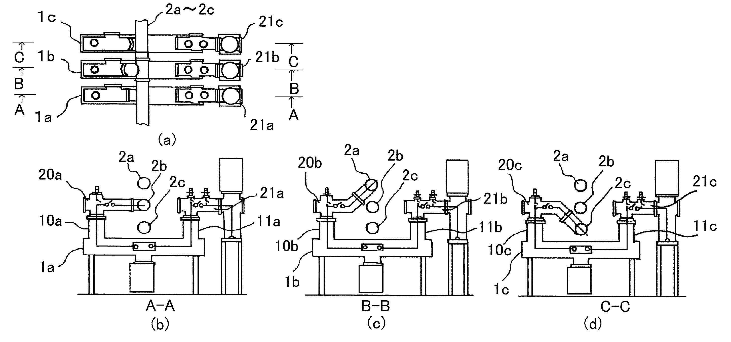
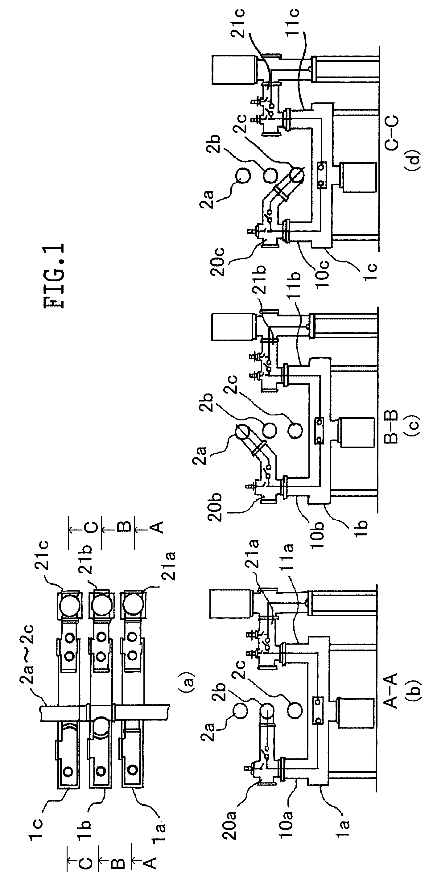
[0020]Embodiments of a gas-insulated switchgear according to the present invention will be explained below, with reference to the accompanying drawings. FIG. 1 is a set of views illustrating a configuration example of a gas-insulated switchgear according to Embodiment 1 of the present invention. Here, constituent elements the same as or equivalent to those in the conventional configuration example, which has been explained with reference to FIG. 7, are indicated by the same reference characters. In FIG. 1, FIG. 1(a) is a plan view; FIG. 1(b) is a cross-sectional view taken along the line A-A in FIG. 1(a); FIG. 1(c) is a cross-sectional view taken along the line B-B in FIG. 1(a); FIG. 1(d) is a cross-sectional view taken along the line C-C in FIG. 1(a). In FIG. 1, reference characters 1a to 1c denote circuit breakers; reference characters 2a to 2c denote main bus bars arranged vertically in parallel with one another; reference characters 10a, 11a, 10b, 11b, 10c and 11c denote lead ex...
embodiment 2
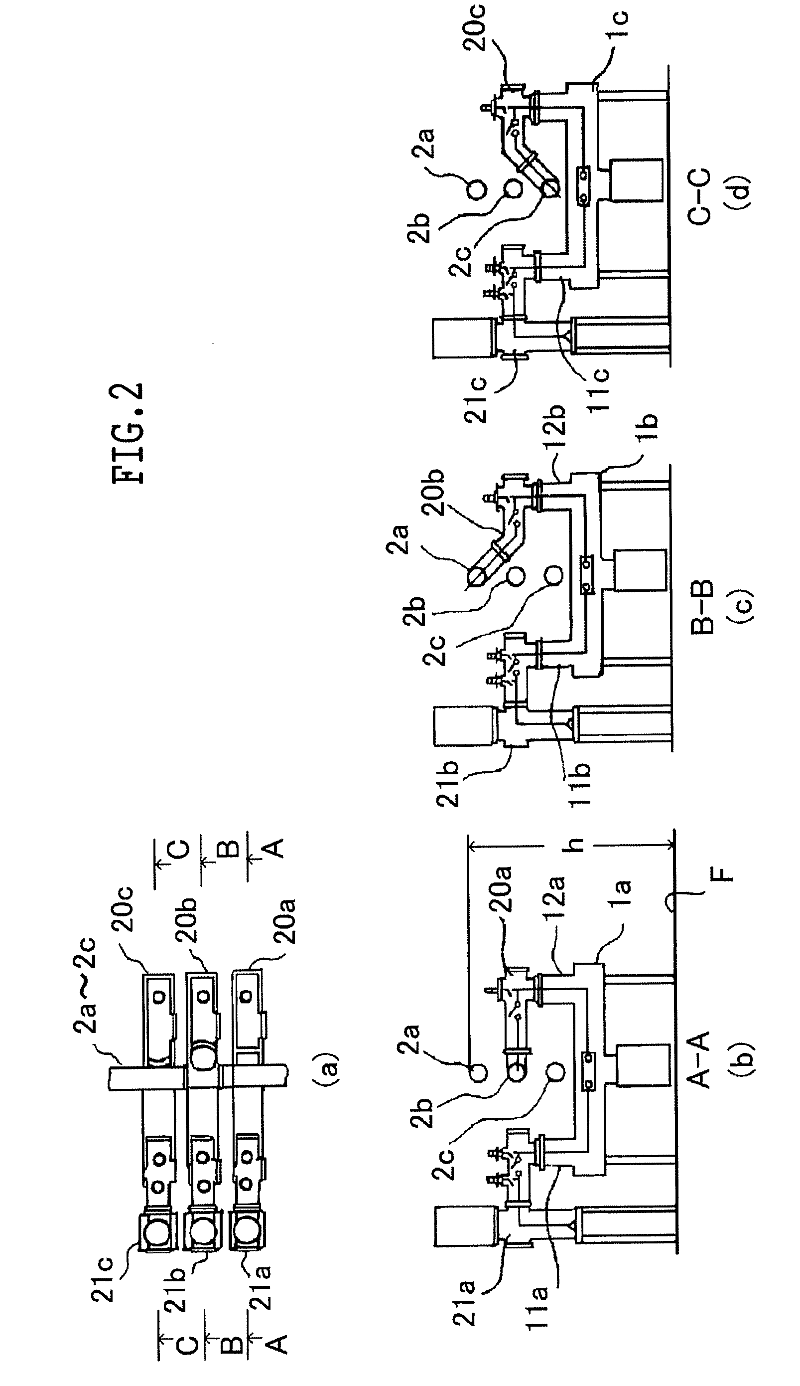
[0025]FIG. 3 is a set of views illustrating a configuration example of a gas-insulated switchgear according to Embodiment 2 of the present invention; the configuration is the same as that of Embodiment 1, except for the arrangement configurations of the main bus bars 2a to 2c. That is to say, in Embodiment 2, two (2b and 2c) out of the main bus bars are vertically arranged in the middle of the space between the lead exit portions of the circuit breakers 1a to 1c, and the other main bus bar 2a is arranged in such a way as to form a right isosceles triangle together with the foregoing two main bus bars.
[0026]FIG. 4 is a set of views illustrating another configuration example of a gas-insulated switchgear according to Embodiment 2, i.e., an example of a case in which the transmission-line connecting terminals 11a, 11b, and 11c are situated at the sides (at the left side of each figure) opposite to those at which the transmission-line connecting terminals 11a, 11b, and 11c are situated ...
embodiment 3
[0028]FIG. 5 is a set of views illustrating a configuration example of a gas-insulated switchgear according to Embodiment 3 of the present invention; an application example is illustrated in which a gas-insulated switchgear is configured with a plurality of groups of main bus bars, each group consisting of three-phase main bus bars. Embodiment 3 is characterized in that, above the main bus bars 2a to 2c of Embodiment 2, the other main bus bars 3a to 3c are arranged in a stacking manner. In other words, by way of other coupling units 22a, 22b and 22c, the other main bus bars 3a to 3c are coupled with the main bus bars 20a, 20b, and 20c, respectively, of Embodiment 2 in such a way as to form right isosceles triangles. The coupling units 22a, 22b, and 22c differ from one another in shape; the coupling units 22a, 22b, and 22c are coupled with the main bus bars 3a, 3b, and 3c, respectively.
[0029]FIG. 6 is a set of views illustrating another configuration example of a gas-insulated switch...
PUM
 Abstract
Description
Claims
Application Information