LED illuminating device and light engine thereof

Inactive Publication Date: 2009-10-29
HON HAI PRECISION IND CO LTD
View PDF4 Cites 33 Cited by
  • Summary
  • Abstract
  • Description
  • Claims
  • Application Information

AI Technical Summary

Problems solved by technology

Therefore, heat dissipation of the LED illuminating device is a problem inhibiting the application of the LED illuminating device, which requires to be resolved.
Otherwise, the brightness, lifespan, and reliability of the LED illuminating device will be seriously affected.
Conventional heat dissipation devices,

Method used


Image

  • LED illuminating device and light engine thereof
  • LED illuminating device and light engine thereof
  • LED illuminating device and light engine thereof

Examples


Embodiment Construction

[0015]Reference will now be made to the drawing figures to describe the various embodiments in detail.

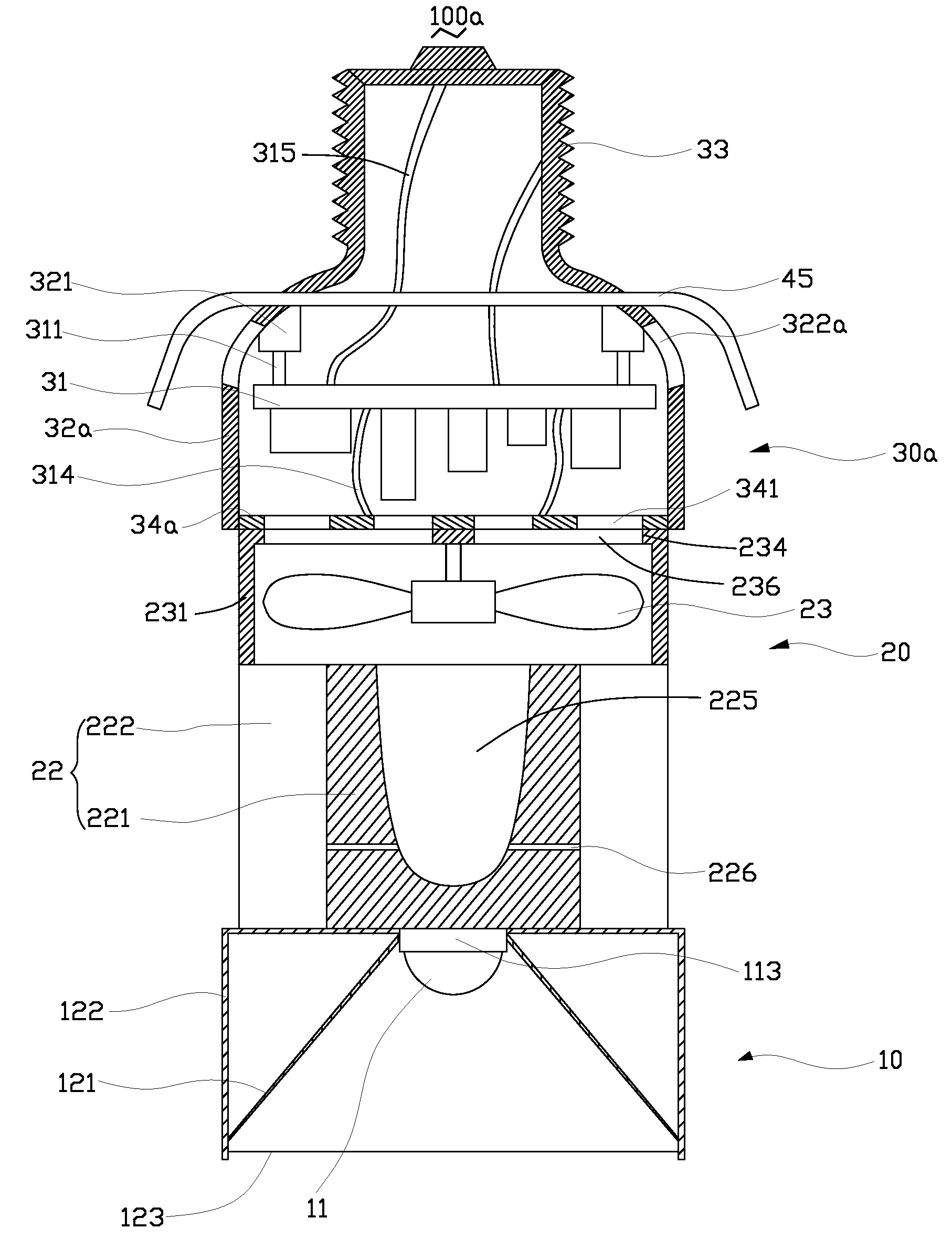
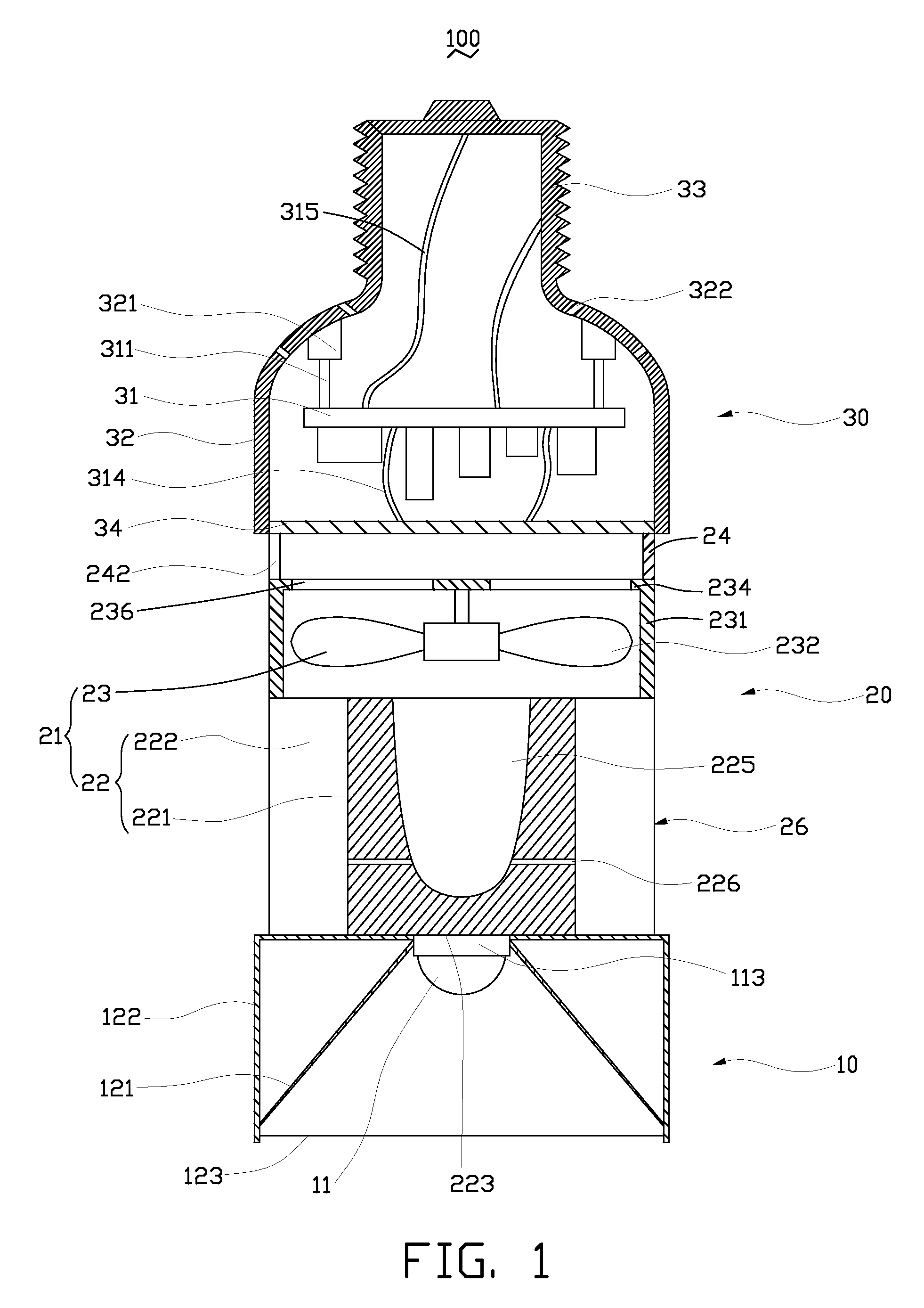
[0016]FIG. 1 is a cross-sectional view of an LED illuminating device 100 in accordance with an embodiment of the present invention. The LED illuminating device 100 includes an optical section 10, an electrical section 30, and a heat dissipation section 20 arranged between the optical section 10 and the electrical section 30. The LED illuminating device 100 is substantially cylindrical. The optical section 10 is located at a front end of the LED illuminating device 100, while the electrical section 30 is located at a rear end of the LED illuminating device 100.

[0017]The optical section 10 includes a housing 122, a light reflector 121, a light source 11, and an optical lens 123. A rear end of the housing 122 is coupled to the heat dissipation section 20, and a front end of the housing 122 is provided with the optical lens 123. The light reflector 121 and the light source 11 are receiv...


PUM


Abstract

An LED illuminating device includes an optical section (10), an electrical section (30), and a heat dissipation section (20). The heat dissipation section is provided with a heat dissipation device (21) which includes a heat sink (22) and a cooling fan (23) provided over the heat sink. The heat sink includes a solid base (231) and a plurality of fins (222) extending radially and outwardly from the base. A blind hole (225) is axially provided in the base. A plurality of air passage holes (226) are radially defined through the base and communicate the blind hole with an outside of the base. The cooling fan provides an airflow towards the heat sink. A portion of the airflow flows through the blind hole and the air passage holes of the base.

Description

CROSS-REFERENCE TO RELATED APPLICATION[0001]Relevant subject matter is disclosed in co-pending U.S. patent application Ser. No. 12 / 255,651 filed on Oct. 21, 2008 and entitled “LED ILLUMINATING DEVICE AND LIGHT ENGINE THEREOF”. The co-pending U.S. patent application is assigned to the same assignee as the instant application. The disclosure of the above-identified co-pending application is incorporated herein by reference.BACKGROUND[0002]1. Technical Field[0003]Embodiments of the present invention generally relate to light emitting diode (LED) illuminating devices, and particularly to an LED illuminating device with a high heat dissipating efficiency and a light engine of the LED illuminating device.[0004]2. Description of Related Art[0005]Presently, LEDs (light emitting diodes) are preferred for use in LED illuminating devices rather than CCFLs (cold cathode fluorescent lamps) due to a high brightness, a long lifespan, and a wide color range of the LED.[0006]For an LED, eighty perce...

Claims


Application Information

Patent Timeline
IPC IPC(8): F21V29/02
CPCF21V29/004F21V29/02F21Y2101/02F21K9/137F21V29/75F21V29/83F21V29/773F21V29/677H01L2924/0002H01L2924/00F21V29/67F21K9/233F21Y2115/10
Inventor LIU, TAY-JIAN
Owner HON HAI PRECISION IND CO LTD
Why Eureka
Try Eureka