Medical x-ray imaging system

a technology of x-ray imaging and x-ray images, which is applied in the field of medical x-ray imaging systems, can solve the problem of not being able to produce a solid-state image pick-up device with such a wide photodetecting surface, and achieve the effect of accurate matching

Active Publication Date: 2009-10-29
HAMAMATSU PHOTONICS KK
View PDF8 Cites 11 Cited by
  • Summary
  • Abstract
  • Description
  • Claims
  • Application Information

AI Technical Summary

Benefits of technology

[0018]It is possible in the medical X-ray imaging system that the number of rows M is smaller than the number of columns N in the photodetecting section, and the photodetecting surface has a rectangular shape whose longitudinal direction is in the row direction. In this medical X-ray imaging system, the reading wire is disposed for each column, so that by thus configuring the photodetecting section, the disposition direction of the reading wires and the shorter side direction of the photodetecting surface match each other. Therefore, the number of pixels (photodiodes) from which charges are read through the reading wires in each frame can be reduced, so that the frame rate (the number of frame data to be output per unit time) can be made higher.
[0019]It is also possible in the medical X-ray imaging system that a rotation center of the solid-state image pick-up device is positioned at one of four corners o

Problems solved by technology

However, due to restrictions in size, etc., of a semiconductor wafer as a material of the photodetecting section of the solid-stat

Method used


Image

  • Medical x-ray imaging system
  • Medical x-ray imaging system
  • Medical x-ray imaging system

Examples


Embodiment Construction

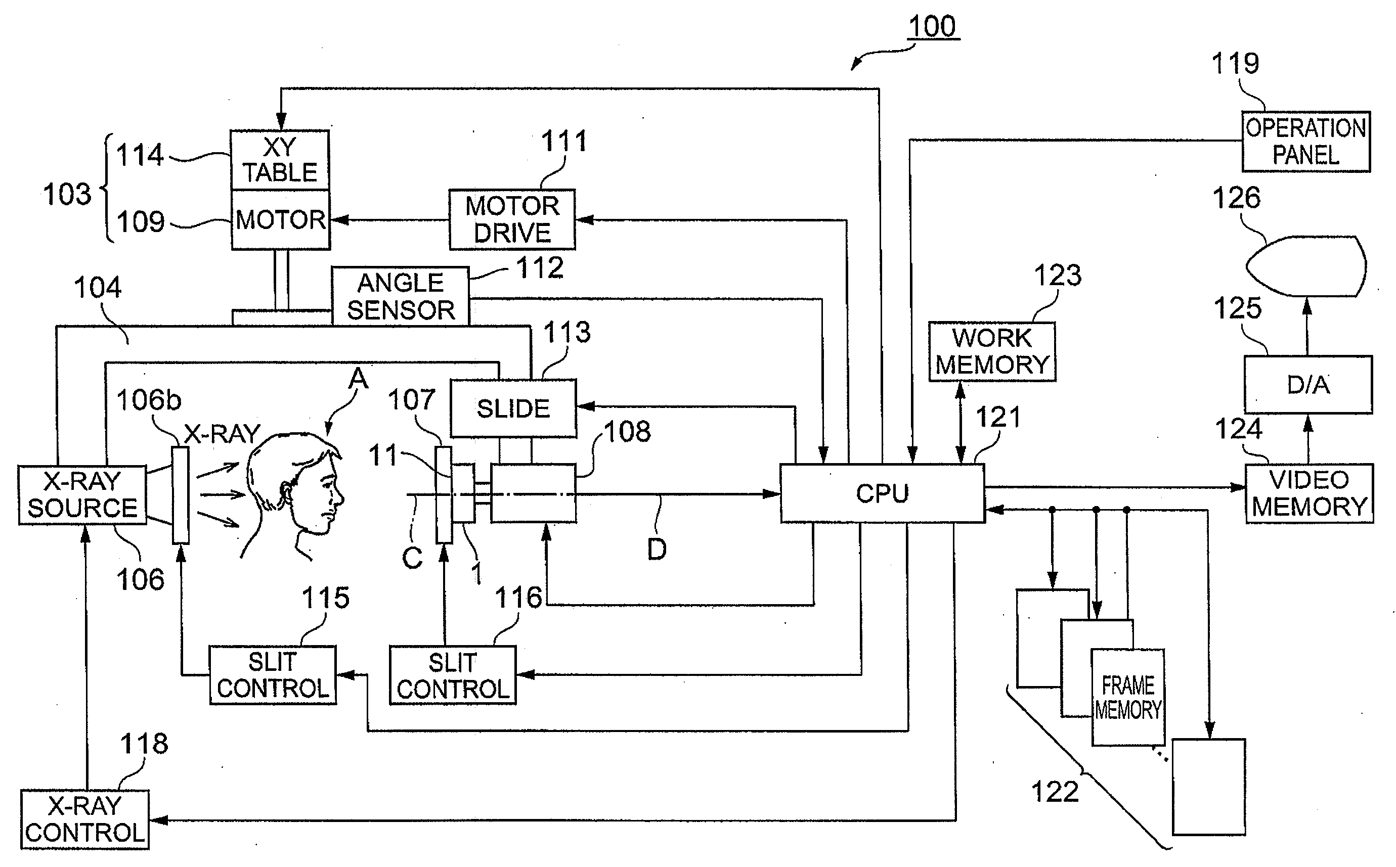
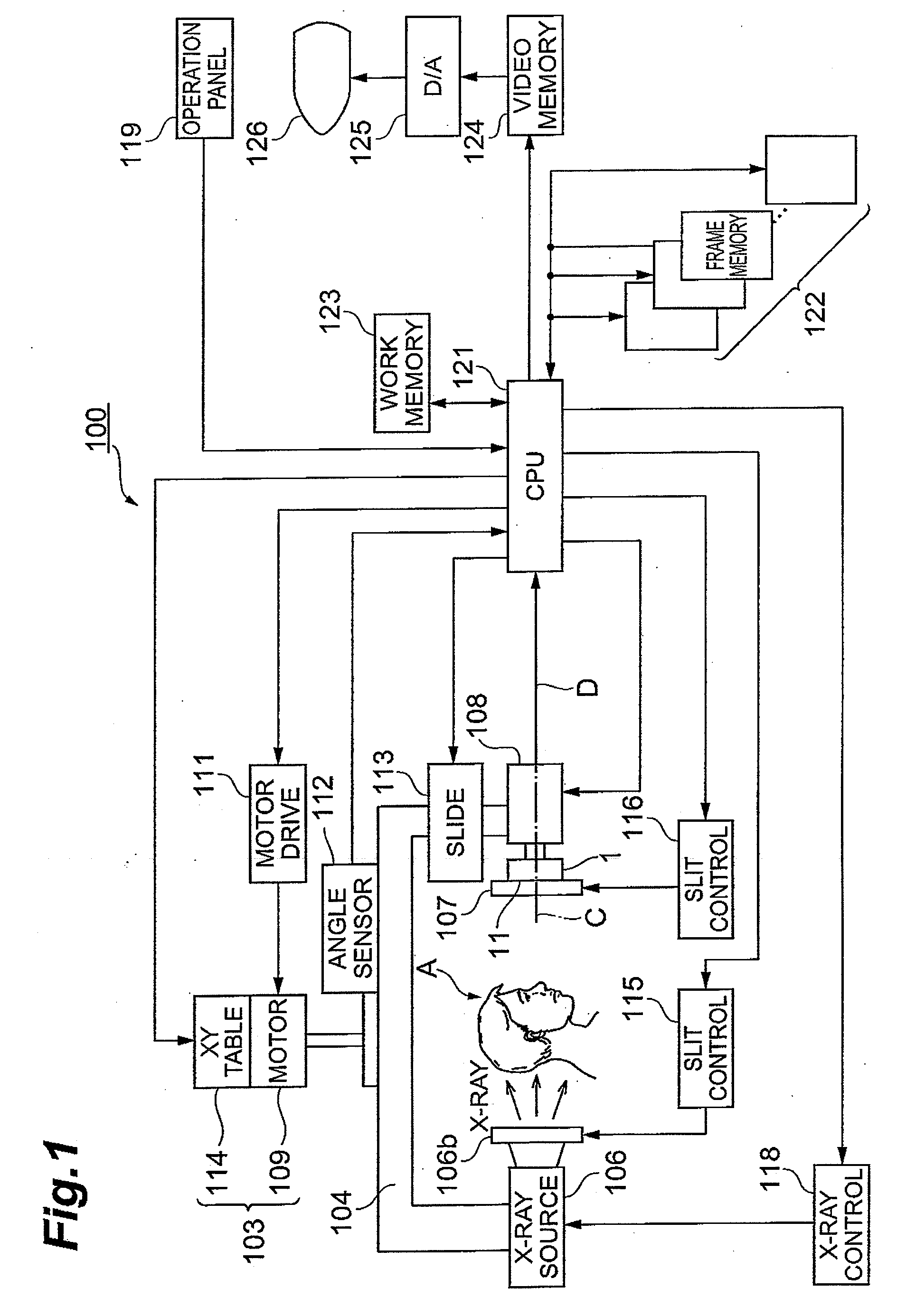
[0043]Hereinafter, a best mode for carrying out the present invention will be described with reference to the accompanying drawings. In the description of the drawings, identical elements are attached with the same reference numerals, and overlapping description is omitted.

[0044]FIG. 1 is a view showing a configuration of a medical X-ray imaging system 100 as an embodiment of the present invention. The X-ray imaging system 100 of the present embodiment has imaging modes for panoramic radiography, cephalometric radiography, and CT, etc., to be used mainly for dental purposes, and images an X-ray image of the jaw of an examinee. The X-ray imaging system 100 includes a solid-state image pick-up device and an X-ray generator, and images an X-ray which is output from the X-ray generator and transmitted through a subject A (that is, the jaw of an examinee) by the solid-state image pick-up device.

[0045]The X-ray imaging system 100 shown in this figure includes the solid-state image pick-up...


PUM


Abstract

The solid-state image pick-up device (1) includes a photodetecting section (10) which is formed by two-dimensionally aligning M×N (M and N are integers not less than 2) pixels in M rows and N columns and has a rectangular photodetecting surface. This solid-state image pick-up device (1) is supported rotatably by a rotation controlling section, and the rotation controlling section controls the rotation angle of the solid-state image pick-up device (1) so that the row direction or column direction of the photodetecting section (10) becomes parallel to the movement direction (B) of the solid-state image pick-up device (1) in one of the two imaging modes, and both of the row direction and the column direction of the photodetecting section (10) tilt with respect to the movement direction (B) of the solid-state image pick-up device (1) in the other imaging mode of the two imaging modes.

Description

BACKGROUND OF THE INVENTION[0001]1. Field of the Invention[0002]The present invention relates to a medical X-ray imaging system.[0003]2. Related Background Art[0004]In medical X-ray photography, in recent years, instead of X-ray sensitive films, X-ray imaging systems using X-ray image pick-up devices have been widely used. Such an X-ray imaging system is convenient such that unlike the X-ray photosensitive film, development is not necessary, and an X-ray image can be confirmed in real time, and is also superior in terms of data storage stability and handling easiness. In X-ray photography for dental diagnosis, such X-ray imaging systems have been increasingly used in various imaging modes for panoramic radiography, cephalometric radiography, and CT.[0005]In the case of a dental X-ray imaging system, the shape of an imaging region required for the X-ray image pick-up device may differ depending on various imaging modes described above. In other words, an imaging region to be used for...

Claims


Application Information

Patent Timeline
IPC IPC(8): A61B6/14
CPCA61B6/14A61B6/4233H04N5/32G01T1/2018H04N5/23238A61B6/5235H04N23/698G01T1/2019G01T1/20184
Inventor MORI, HARUMICHIKYUSHIMA, RYUJIFUJITA, KAZUKI
Owner HAMAMATSU PHOTONICS KK
Why Eureka
Try Eureka