Intermediate adapter, camera body and imaging system

Active Publication Date: 2009-10-29
PANASONIC CORP
View PDF8 Cites 84 Cited by
  • Summary
  • Abstract
  • Description
  • Claims
  • Application Information

AI Technical Summary

Benefits of technology

[0014]In accordance with the aforementioned aspects, upon attaching an interchangeable lens to an intermedi

Problems solved by technology

However, when the power-supply voltage is supplied from the camera body to the interchangeable lens while attaching the interchangeable lens

Method used


Image

  • Intermediate adapter, camera body and imaging system
  • Intermediate adapter, camera body and imaging system
  • Intermediate adapter, camera body and imaging system

Examples


embodiment 1

1. Structure

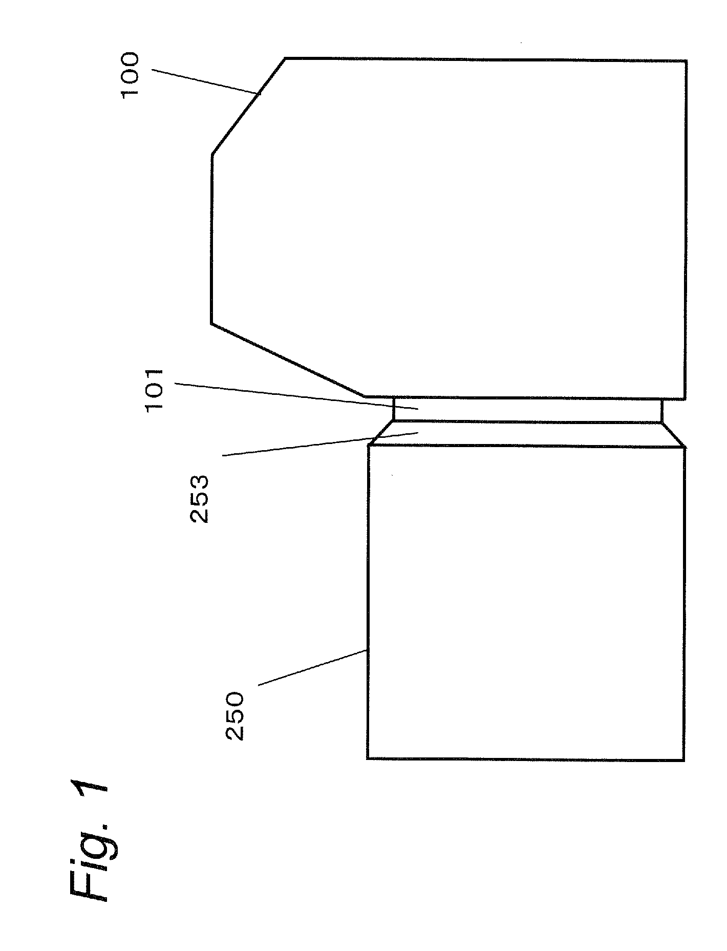
[0023]FIG. 1 is a schematic view showing an imaging system with an interchangeable lens 250 directly attached to a camera body 100. A mount 101 used for attaching the interchangeable lens 250 in a bayonet system is provided on the camera body 100. Here, the interchangeable lens 250 is a lens directly mountable to the camera body 100.

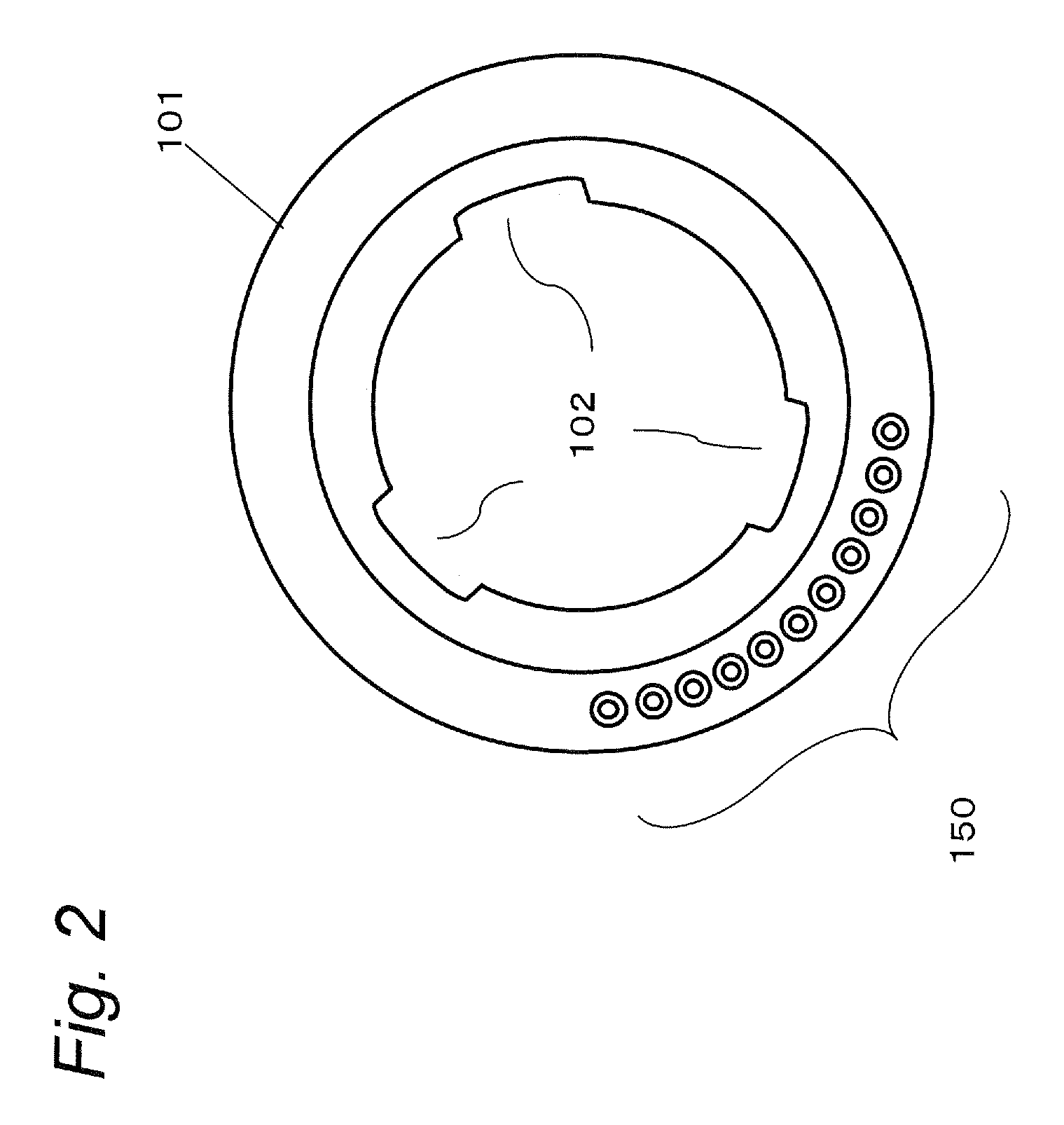
[0024]FIG. 2 is a view showing the mount 101 of the camera body 100 viewed from the front side. The interchangeable lens 250 directly mountable to the camera body 100 can be directly attached to the camera body 100 by inserting a claw (not shown) formed on a joining portion 253 (see FIG. 1) of the interchangeable lens 250 into a cut-out portion 102 of the mount 101 of the camera body 100 and rotating the lens 250 clockwise. Terminals 150 for communicating with the interchangeable lens 250 are provided on the mount 101 of the camera body 100.

[0025]Here, when the shape of the joining portion (203) of the interchangeable lens does not match the ...

embodiment 2

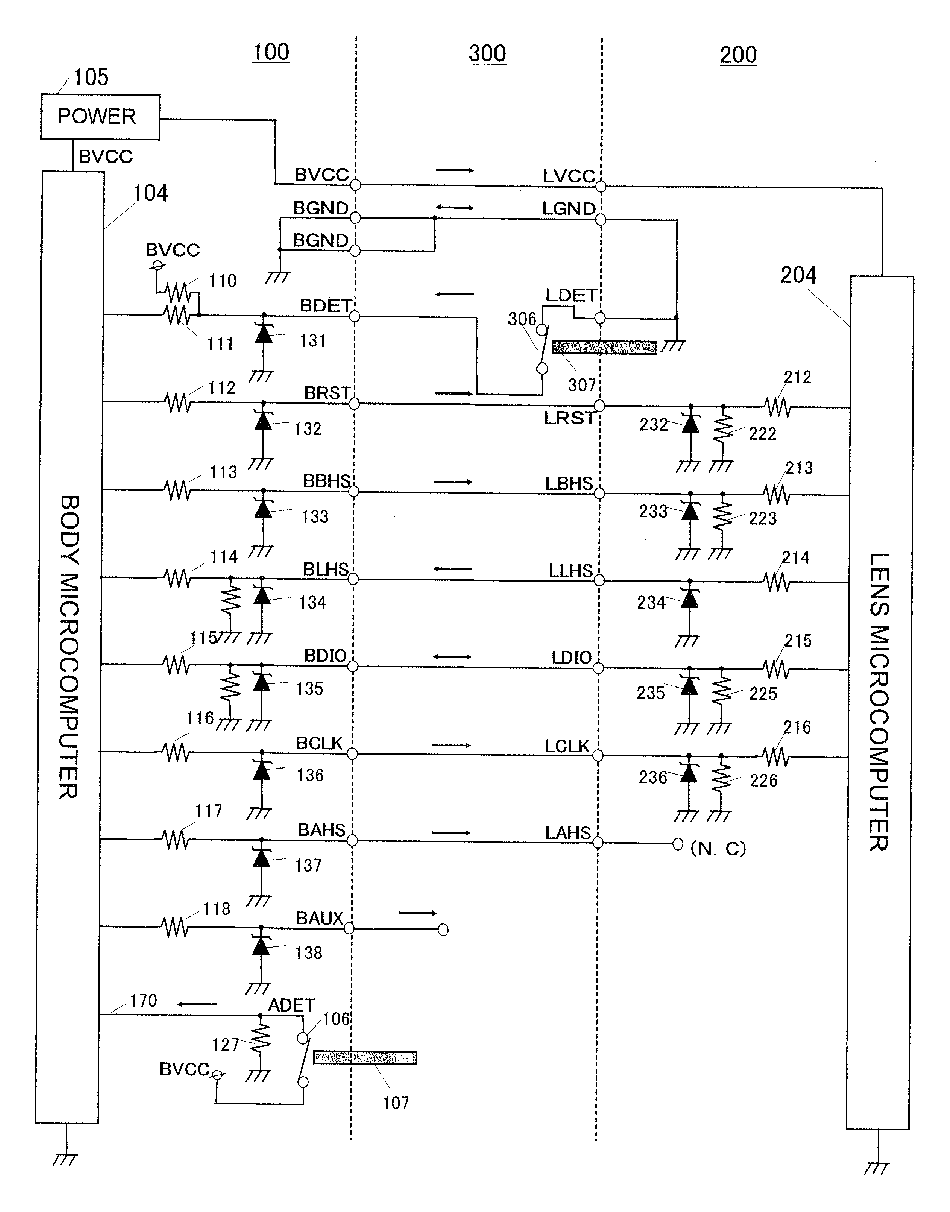
[0048]FIG. 7 shows another example of structure (wiring diagram) of an imaging system. The intermediate adapter 300 and the camera body 100 shown in FIG. 7 differ from those in the structure shown in FIG. 6 of embodiment 1 in structure relating to the switch 106 and the pin 107 for detecting attachment of the adapter. More specifically, in the structure of FIG. 7, the switch 106 and the pin 107 for detecting attachment of the adapter are removed from the camera body 100 in the structure shown in FIG. 6, and in place of these, a switch 308 and a pin 309 for detecting attachment of the adapter are installed in the intermediate adapter 300. Here, a detection unit related to BDET 154 includes a switch 306 and a pin 307 in the same manner as in the structure shown in FIG. 6. Moreover, a terminal (not shown) on the intermediate adapter 300 side for BDET 154 and a terminal (not shown) on the intermediate adapter 300 side for ADET 170 form one example of an informing unit. The other structu...

embodiment 3

[0052]Embodiments 1 and 2 have explained the structure capable of detecting the attachment or not-attachment of the adapter 300 and the interchangeable lens 200 to the camera body 100. The present embodiment will discuss a structure for preventing an erroneous detection during an operation for attaching the intermediate adapter 300 and the interchangeable lens 200.

[0053]The structure of the imaging system of the present embodiment is basically the same as that explained in embodiment 1, however, it differs from embodiment 1 in operations of the switch 106 and the switch 306. Referring to FIG. 8, the following description will discuss the operations of the switch 106 and the pin 107 of the present embodiment.

[0054]FIG. 8A is a view showing status of the switch 106 and the pin 107 when no intermediate adapter 300 is attached to the camera body 100. FIG. 8B is a view showing status of the switch 106 and the pin 107 while the intermediate adapter 300 is being attached to the camera body...


PUM


Abstract

An intermediate adapter includes a first terminal operable to be electrically connected to a lens detecting terminal provided on the camera body when the intermediate adapter is attached to the camera body, a second terminal operable to be electrically connected to a terminal provided on the interchangeable lens for providing a ground potential when the interchangeable lens is attached to the intermediate adapter, and a first switch interposed between the first terminal and the second terminal. The first switch is operable to electrically connect the first terminal and the second terminal when the first switch is on, and disconnect the electrical connection between the first terminal and the second terminal when the first switch is off. While the intermediate adapter is being attached to the interchangeable lens, the first switch is off to disconnect the electrical connection between the first terminal and the second terminal.

Description

BACKGROUND[0001]1. Technical Field[0002]The technical fields relates to an intermediate adapter used for using an interchangeable lens which is not directly fitted to a camera body, that is to be interposed between the camera body and the interchangeable lens.[0003]2. Related Art[0004]In order to use an interchangeable lens that is not directly fitted to a camera body, an intermediate adapter that is interposed between the camera body and the interchangeable lens has been known. The intermediate adapter is used in such a way that the intermediate adapter is first attached to the camera body and then the interchangeable lens is attached to the intermediate adapter. The intermediate adapter is provided with terminals corresponding to the respective signal terminals, power-supply terminals and the like of the camera body and the interchangeable lens. Communication between the camera body and the interchangeable lens are conducted through the terminals of the intermediate adapter.[0005]...

Claims


Application Information

Patent Timeline
IPC IPC(8): G03B17/14
CPCG03B17/14
Inventor UEDA, HIROSHISHIBUNO, KOJINAKAJIMA, HIDEKAZUOOTSUKA, MICHIHIKO
Owner PANASONIC CORP
Why Eureka
Try Eureka