Occipitocervical Fixation System

a fixation system and occipital plate technology, applied in the field of occipital plate system, can solve the problems of increasing the complexity of the system, complicating the installation, adding bulk to the system, and presenting additional challenges to the occipital area for implantation, so as to avoid the complexity and bulk of external nuts and support platforms

Active Publication Date: 2009-10-29
AESCULAP IMPLANT SYST
View PDF22 Cites 61 Cited by
  • Summary
  • Abstract
  • Description
  • Claims
  • Application Information

AI Technical Summary

Benefits of technology

[0009]The present invention provides an occipital plate system having adequate contact area between the spinal rods and the plate to rigidly secure the two, while avoiding the complexity and bulk of external nuts and support platforms. To this end, the occipital plate system of the present invention is configured such that the contact area between the rod and the occipital plate lies within the confines of the rod receptacle. That is, rather than having a fastener slide within an aperture of the occipital plate (in which the contact area is limited to just a portion of the aperture's edge around the fastener), the present invention provides an occipital plate system in which a rail of the occipital plate slides within the rod receptacles.
[0010]This configuration provides for a number of benefits. First, the entire width of the rail is used as contact area in contrast to the prior art in which only the edge of the aperture about the fastener is used. This eliminates the need for a support platform or similar component to increase contact area, thereby simplifying the occipital plate system of the present invention and minimizing its size.
[0011]Additionally, since the rail does not need to accommodate an aperture for the bolt, a more slender rail can be used. This has the advantage of reducing the form factor of the occipital plate system which is critical in the confined space of the occiput. Furthermore, by reducing the size of the rails, a larger occipital plate can be used which has a larger surface with additional apertures for bone screws. A larger occipital plate with additional bone screws equates to a more robust connection to the skull.
[0012]Finally, the contact area between the rod and the occipital plate is situated directly below the set screw. This results in a direct line of contact among the components within the confines of the rod receptacle, thereby optimizing the compressive force imparted by the set screw and eliminating the need for an external nut as used in the prior art. This has the benefit of, not only maintaining a small form factor, but also optimizing the force of the set screw to hold the rod rigidly with respect to the plate.

Problems solved by technology

Although spinal systems for the lumbar and the thoracic areas of the spine have been developed to meet these design criteria, the occipitocervical area presents additional challenges for implantation given its smaller size and increased concentration of nerves and arteries which need to be identified and avoided.
For example, it adds another component to the occipital plate system, which, in turn, increases the complexity of the system and complicates its installation.
Additionally, because the support platform encircles bolt, it adds bulk to system, which can be problematic given the restricted space of the occiput.

Method used


Image

  • Occipitocervical Fixation System
  • Occipitocervical Fixation System
  • Occipitocervical Fixation System

Examples


Embodiment Construction

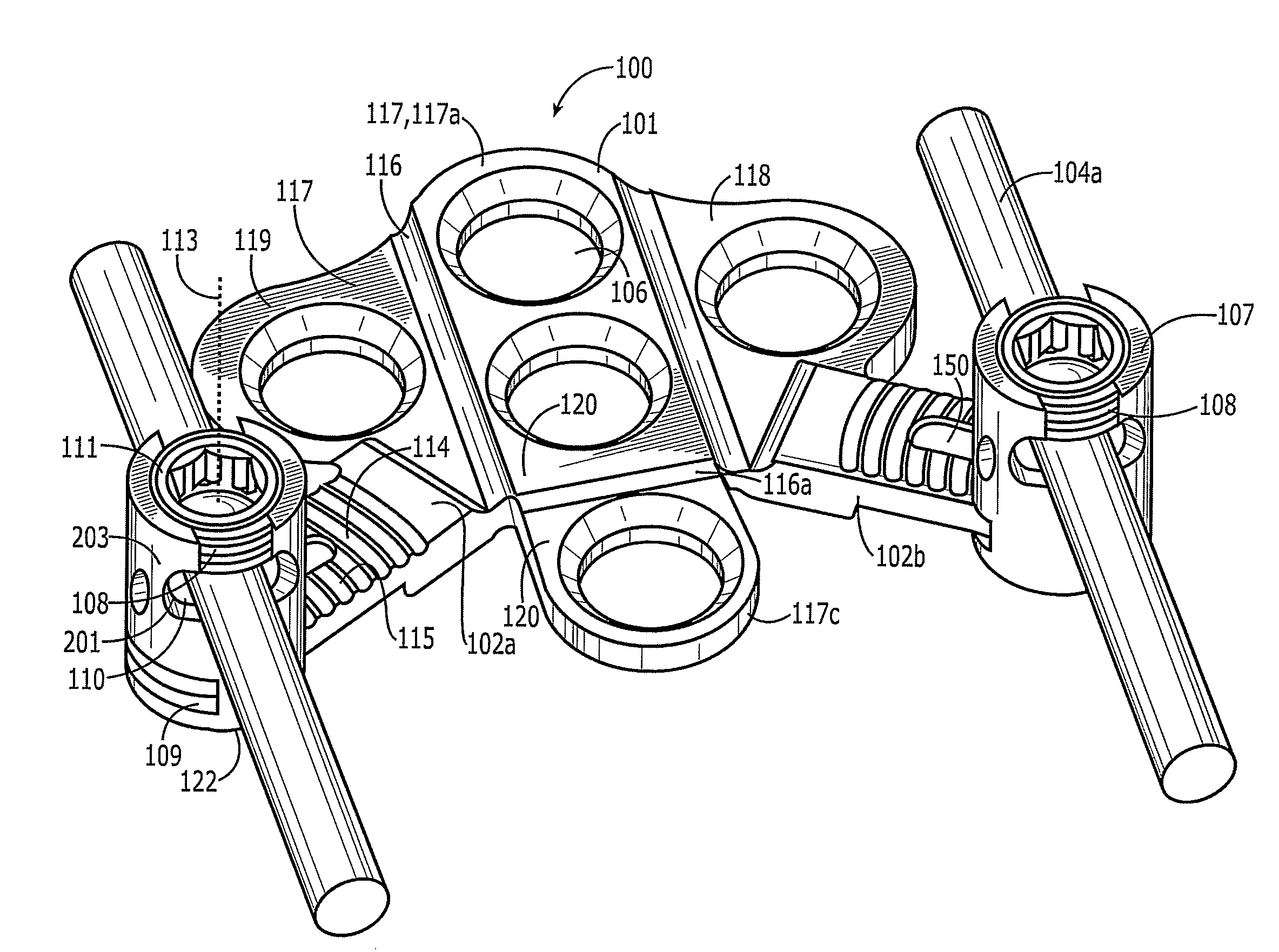
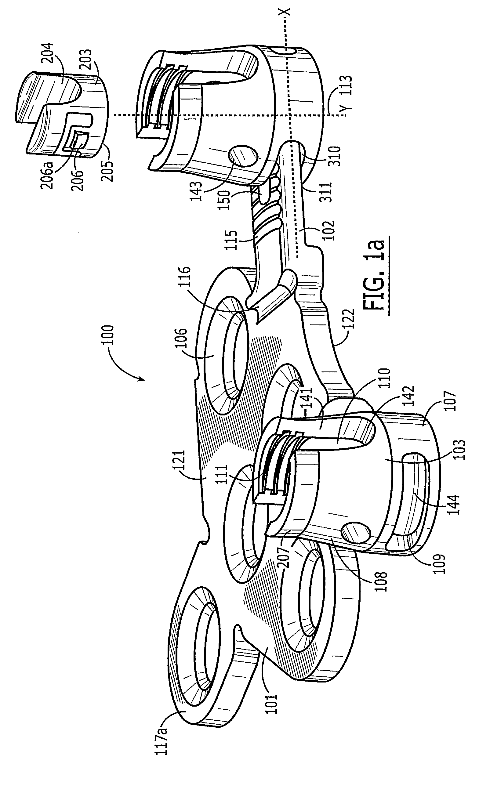
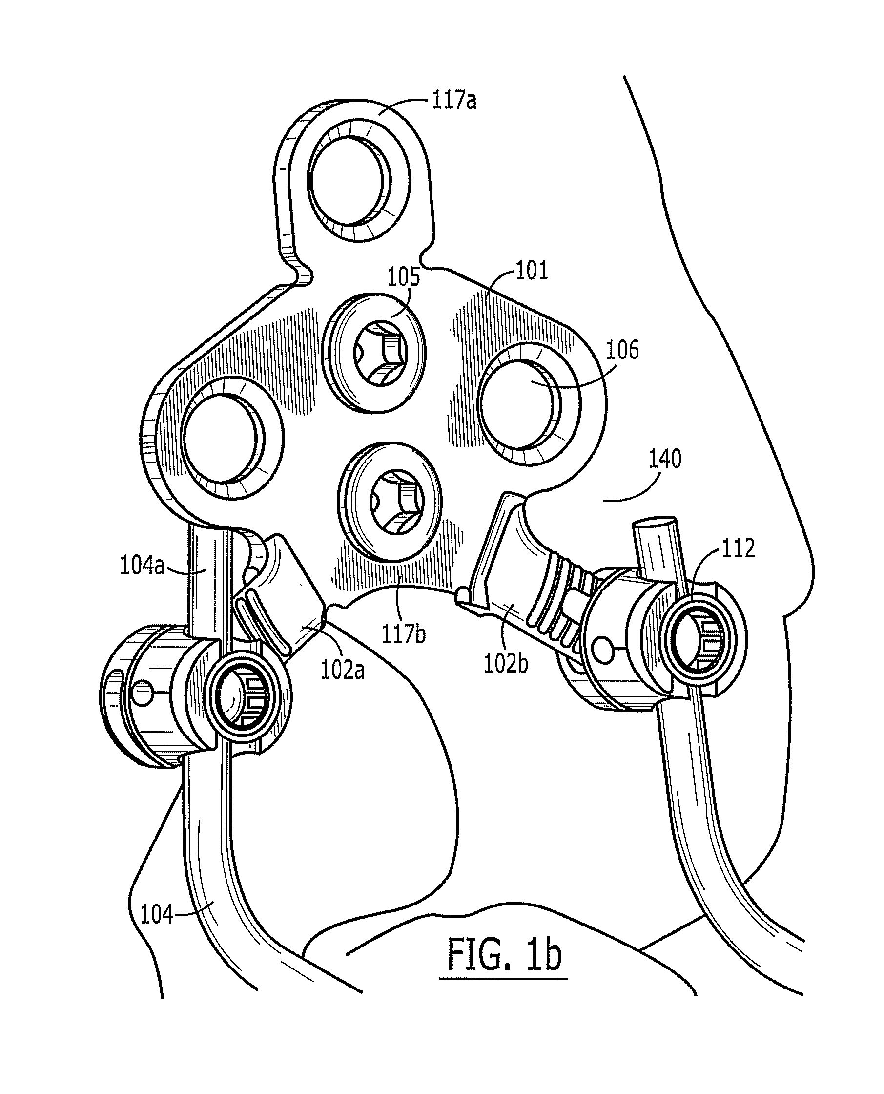
[0021]Referring to FIGS. 1(a) and 1(b) perspective views of a preferred embodiment of an occipital plate system 100 of the present invention are shown. The occipital plate system 100 is suitable for securing distal ends 104a of spinal rods 104 to the occiput of a patient's skull 140. For purposes of describing the relative position of various elements of the system, the system is deemed to have a top 121 (which, in FIG. 1 projects out of the page), a bottom 122 (which projects into the page), a superior end 117a (toward the top of the page), and an inferior end 117b (toward the bottom of the page). It should be understood that this orientation is for descriptive purposes only and should not be used to limit the scope of the invention.

[0022]The occipital plate system 100 comprises: (a) a plate 101 having one or more apertures 106 for receiving bone fasteners 105 adapted for securing the plate 101 to the patient's skull; (b) two rails 102a, 102b extending outwardly from the plate 101;...


PUM


Abstract

An occipital plate system comprising: (a) a plate having one or more apertures for receiving bone fasteners adapted for securing the plate to the skull; (b) two rails extending outwardly from opposing sides of the plate; and (c) two rod receptacles, each comprising a body portion and a receiver portion, the body portion defining a passageway through which one of the rails slides, the receiver portion defining a cavity to receive a rod and threads above the cavity for receiving a set screw such that at least a portion of each of a rail, the rod and the set screw are contained within the rod receptacle.

Description

REFERENCE TO RELATED APPLICATIONS[0001]This application is a national stage of PCT Application No. PCT / US06 / 037385, filed Sep. 25, 2006 which claims priority to U.S. Provisional Application No. 60 / 722,310, filed on Sep. 30, 2005, which is hereby incorporated by reference.FIELD OF THE INVENTION[0002]The present invention is related to a system for stabilizing the spine. More particularly, the present invention is related to an occipital plate system, which secures a cervical fixation system to a patient's occiput.BACKGROUND OF INVENTION[0003]Occipitocervical fixation systems provide stabilization of the base of the skull (or occiput) with respect to the neck. To function effectively, occipitocervical fixation systems should meet a number of design criteria. For example, such systems must be extremely strong and rigid, yet be minimally invasive and have a low profile. Such systems should also be relatively easy to assemble, implant, and maintain. Although spinal systems for the lumbar...

Claims


Application Information

Patent Timeline
Patent Type & Authority Applications(United States)
IPC IPC(8): A61B17/70A61B17/58
CPCA61B17/7011A61B17/7055A61B17/7044
Inventor WING, CHARLES A.CREWS, ROBERT M.USHER, JR., JOHN A.
Owner AESCULAP IMPLANT SYST
Why Eureka
Try Eureka