Ribbon Needle Loom for Manufacturing a Strip, in Particular a Label Strip, Having a Woven-In Conductive Thread, in Particular Antenna Thread

Inactive Publication Date: 2009-11-05
TEXTILMA AG
View PDF10 Cites 15 Cited by
  • Summary
  • Abstract
  • Description
  • Claims
  • Application Information

AI Technical Summary

Benefits of technology

[0011]To avoid damage to the ribbon fabric and/or to the ribbon needle loom, the blade may be provided with a predetermined breaking point which lies outside the weaving region and which is activated in

Problems solved by technology

However, more details of this canno

Method used


Image

  • Ribbon Needle Loom for Manufacturing a Strip, in Particular a Label Strip, Having a Woven-In Conductive Thread, in Particular Antenna Thread
  • Ribbon Needle Loom for Manufacturing a Strip, in Particular a Label Strip, Having a Woven-In Conductive Thread, in Particular Antenna Thread
  • Ribbon Needle Loom for Manufacturing a Strip, in Particular a Label Strip, Having a Woven-In Conductive Thread, in Particular Antenna Thread

Examples


Embodiment Construction

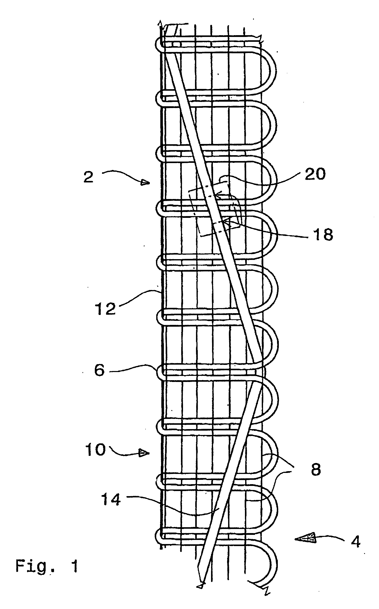
[0019]FIG. 1 shows a ribbon fabric 2 in which weft thread loops 6 are inserted from an insertion side 4 between warp threads 8. On the side 10 lying opposite the insertion side 4, the weft thread loops 6 are mutually tied off by means of stitches 12 indicated diagrammatically as a line. A conductive thread 14 runs, zigzag-shaped, on the topside of the ribbon fabric 2 and is tied in at the turning points 16 in each case by means of a weft thread loop 6. The conductive thread 14 serves as an antenna and is interrupted at 18 before the application of a transponder chip 20 which is connected to the two ends of the conductive thread. Such a connection may be implemented, for example, by welding, soldering, bonding with an electrically conductive adhesive, crimping of clamping.

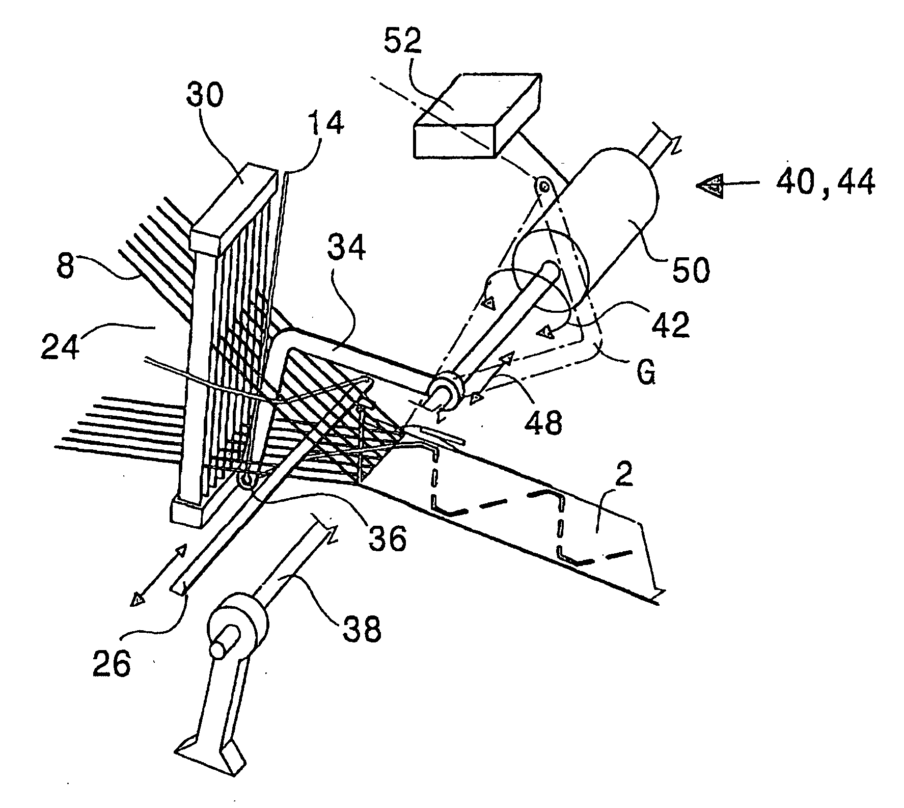
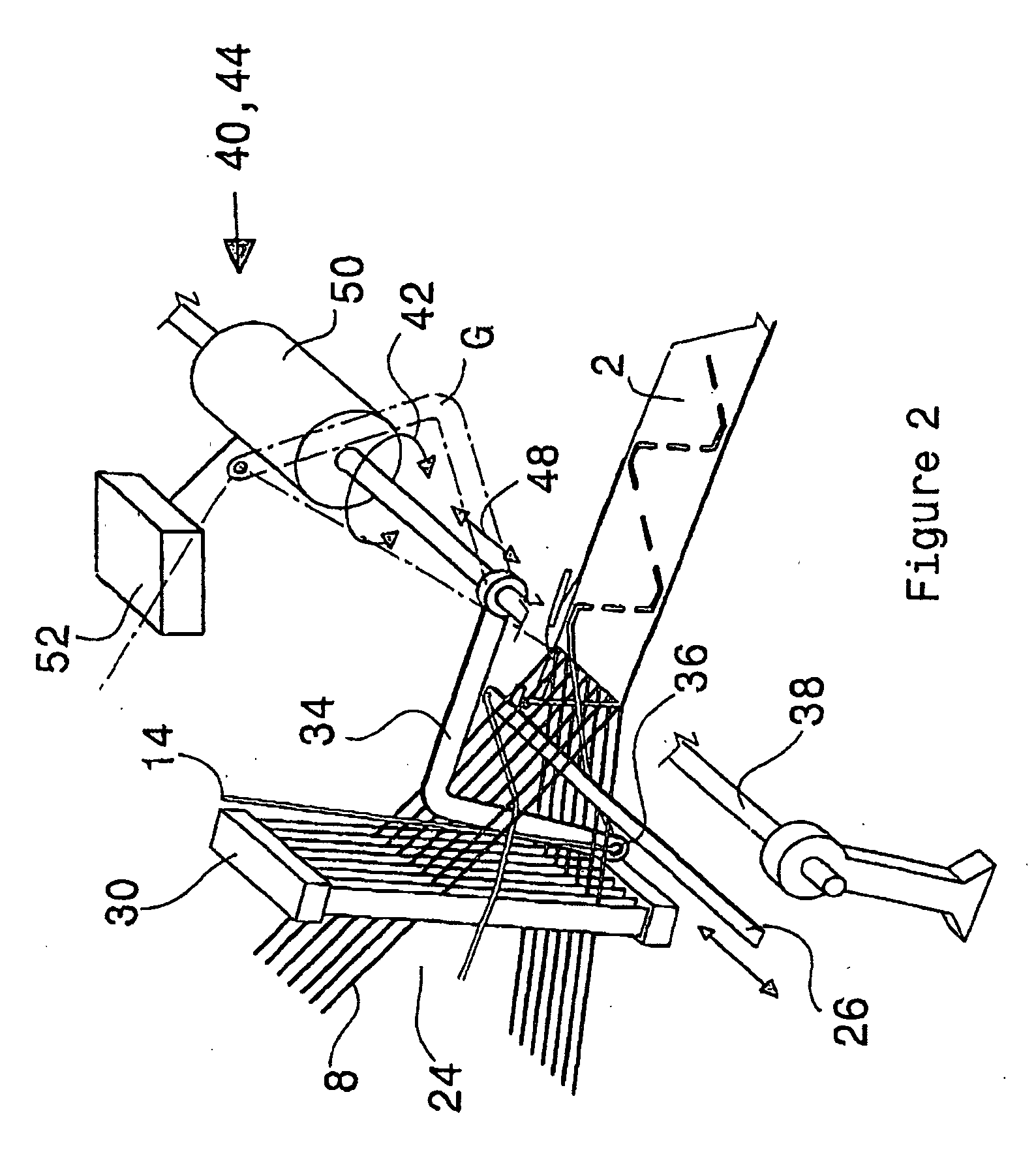
[0020]FIG. 2 shows diagrammatically a ribbon needle loom 22 which is suitable for manufacturing a ribbon fabric 2 of FIG. 1 with a conductive thread 14, but without a transponder chip 20. Warp threads 8 are opened b...


PUM

PropertyMeasurementUnit
Electrical conductoraaaaaaaaaa
Widthaaaaaaaaaa
Breaking strengthaaaaaaaaaa

Abstract

In order to make it possible to weave in a conductive thread, in particular an antenna thread, in a very wide variety of ways in a ribbon needle loom for manufacturing a strip, in particular a label strip, having a shedding apparatus for forming a shed (24) from warp threads (8), a weft insertion needle (26) for inserting weft thread loops, a reed (30) and having a feed apparatus (34) for a thread which has a blade (34) which dips into the shed (24) between warp threads (8) as far as under the insertion path of the weft insertion needle (26), it is proposed that the blade is arranged on a shaft (38) which is oriented transversely with respect to the warp direction. The shaft is connected to a first drive apparatus (40a) for performing a pivoting movement of the shaft. As a result of the pivoting, the blade (34) dips into and out of the shed (24). Furthermore, the shaft is connected to a second drive apparatus (44a) for movement in the axial direction. As a result, the blade (34) can be moved over the width of the strip (2).

Description

[0001]This application claims priority of PCT application PCT / CH2005 / 000772 having a priority date of Dec. 23, 2005, the disclosure of which is incorporated herein by reference.TECHNICAL FIELD[0002]The invention relates to a ribbon needle loom for manufacturing a strip, in particular a label strip, having a woven-in conductive thread, in particular antenna thread.BACKGROUND OF THE INVENTION[0003]A ribbon needle loom of the type initially mentioned is known from CH 490 581. There, the fancy threads are arranged by means of a blade during the weaving of a strip. How the blade is to be actuated cannot be gathered from the publication. There are also no suggestions to be found that the ribbon needle loom could be suitable for weaving in a conductive thread, in particular an antenna thread.[0004]WO 2005 / 071605 describes a textile material with an antenna and with an RF transponder. The textile material can be manufactured by means of a weaving technique. However, more details of this can...

Claims


Application Information

Patent Timeline
IPC IPC(8): D03D35/00D03D13/00D03D47/02D03D15/00
CPCD03D1/0088D03D31/00D03D35/00D03D41/00D10B2401/16D10B2401/18D03D13/002D03D47/02
Inventor SPEICH, FRANCISCO
Owner TEXTILMA AG
Why Eureka
Try Eureka