

Inductive module
a technology of inductive modules and modules, applied in the direction of magnets, inductances, magnetic bodies, etc., can solve the problems of low productivity, time-consuming and costly manufacturing processes, and manual labor
- Summary
- Abstract
- Description
- Claims
- Application Information
AI Technical Summary
Benefits of technology
Problems solved by technology
Method used
Image

Examples
Embodiment Construction
[0047]Before the present invention is described in greater detail, it should be noted that like elements are denoted by the same reference numerals throughout the disclosure.
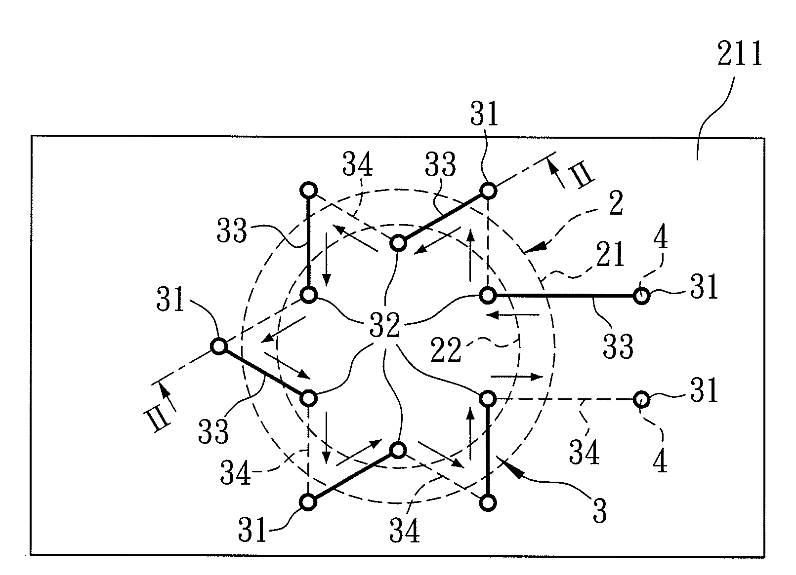
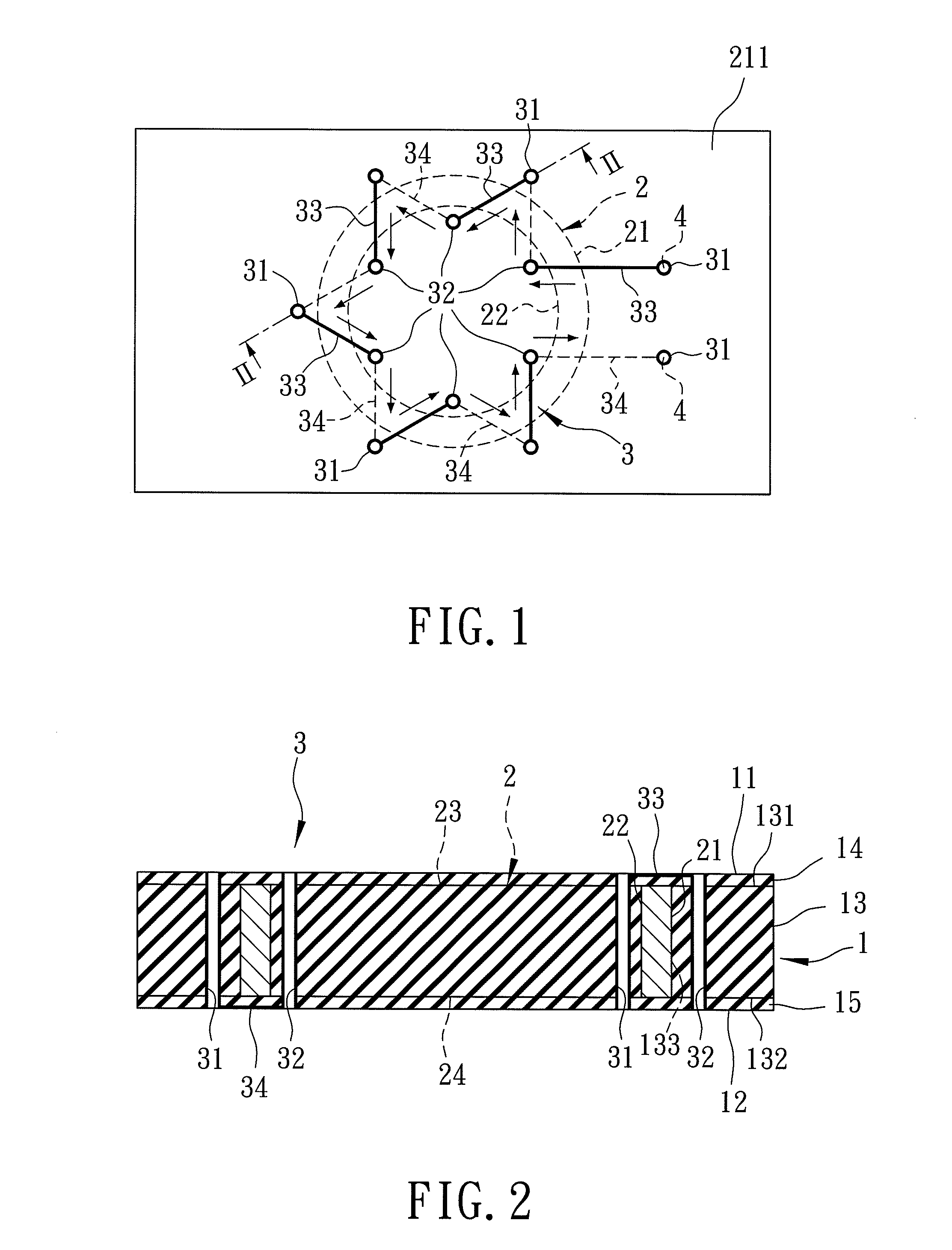
[0048]Referring to FIG. 1 and FIG. 2, the first preferred embodiment of an inductive module according to the present invention is embodied in an inductor, and includes an electrically insolating basic substrate unit 1, a first core unit 2, a first coil unit 3, and a plurality of conductive contacts 4.
[0049]The basic substrate unit 1 has opposite first and second trace-forming sides 11, 12.
[0050]The first core unit 2 is made from a ferromagnetic material, such as cobalt (Co), iron (Fe), nickel (Ni) etc. The first core unit 2 is embedded in the basic substrate unit 1, and has a pair of opposite first and second vertical sides 21, 22 and a pair of opposite first and second horizontal sides 23, 24. The first and second horizontal sides 23, 24 are substantially parallel to the first and second trace-forming sides 11,...
PUM
| Property | Measurement | Unit |
|---|---|---|
| Current | aaaaa | aaaaa |
| Electrical conductor | aaaaa | aaaaa |
| aaaaa | aaaaa |
Abstract
Description
Claims
Application Information