
Safety cone placing device and method

a safety cone and placing device technology, applied in the field of road safety, can solve the problems of inability to place cones in a particular place in an automatic fashion from a moving vehicle, inability to deliver cones to a particular place, and inability to meet the needs of traffic signals, etc., to achieve the effect of reducing the time it takes to deliver and place safety cones, reducing disturbances, and improving safety

Inactive Publication Date: 2009-11-05
WORLDWIDE SAFETY
View PDF5 Cites 4 Cited by
  • Summary
  • Abstract
  • Description
  • Claims
  • Application Information

AI Technical Summary

Benefits of technology

"The present invention provides a device, method, and system for automatically placing safety cones on a ground surface from a moving vehicle. The device includes a receptacle for holding a plurality of safety cones, with a releasing means for releasing one safety cone at a time. The safety cones have a flexible means that can resist perturbations and easily release from the receptacle. The device can be controlled by a control means and can be used with modular components. The technical effect of the invention is that it provides an efficient and safe way to place safety cones on the ground surface from a moving vehicle."

Problems solved by technology

This task is labor-intensive, slow and could easily result in chronic back-injuries in those individuals who perform such a task routinely.
However, with the current safety cones, being fairly rigid and having a tendency to easily fall over, placing the cones to a particular place in an automatic fashion from a moving vehicle would not be practical.
Therefore, previous attempts of cone delivery or placing devices have not been successful.

Method used


Image

  • Safety cone placing device and method
  • Safety cone placing device and method
  • Safety cone placing device and method

Examples


Embodiment Construction

[0045]Although the following detailed description contains many specifics for the purposes of illustration, anyone of ordinary skill in the art will readily appreciate that many variations and alterations to the following exemplary details are within the scope of the invention. Accordingly, the following preferred embodiment of the invention is set forth without any loss of generality to, and without imposing limitations upon, the claimed invention.

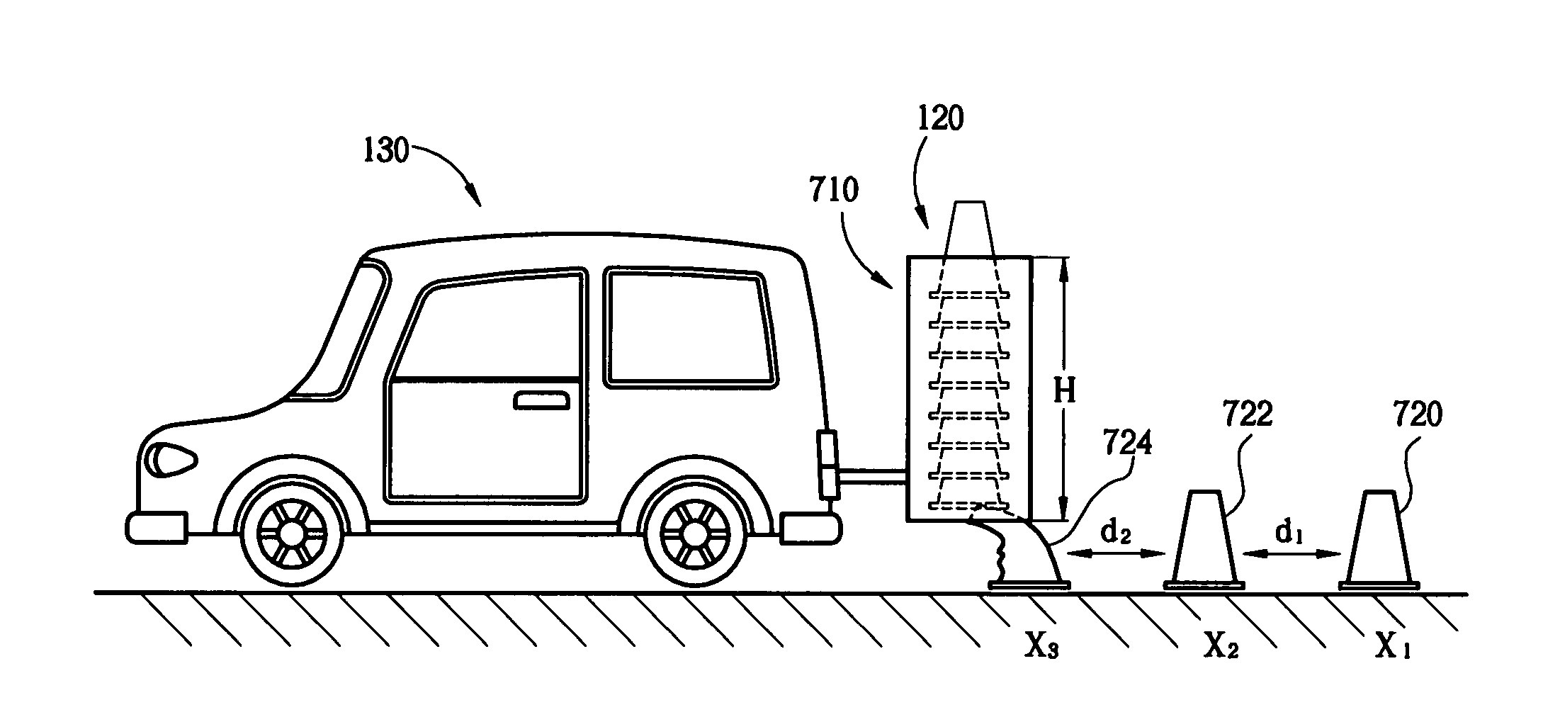
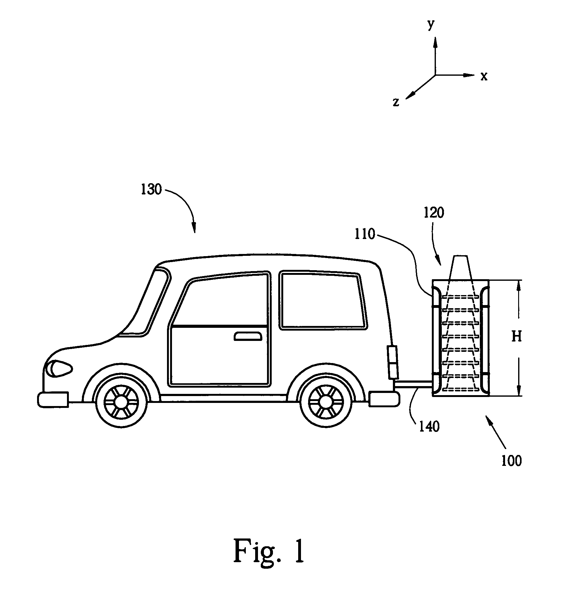
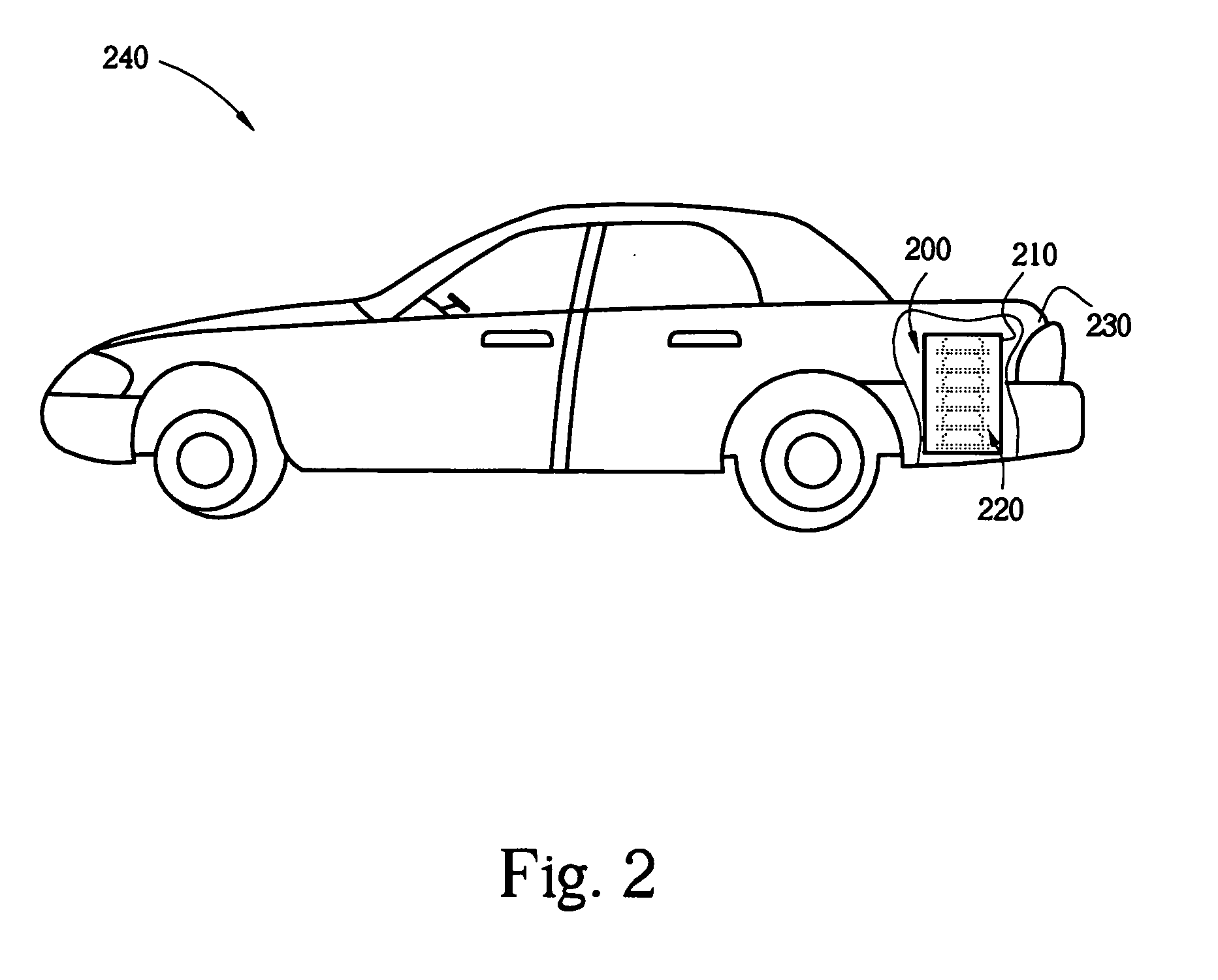
[0046]The present invention provides a device, method and system for automatically placing a safety cone to a desired position on a ground surface from a moving vehicle. The key idea of the present invention is that there is a receptacle that holds a plurality of safety cones. A releasing means which is attached to the receptacle is controlled and advances the safety cones in an automatic and controlled fashion, one-by-one, to desired locations on a road, street, freeway, intersection, or the like.

[0047]FIG. 1 shows a device 100 that incl...


PUM


Abstract

Automatic placement of safety cones from a moving vehicle is provided. The preferred safety cone would have a flexible cone part. A receptacle holds a plurality of safety cones either with the flexible cone part in non-compressed position or in spring-loaded position. The receptacle is removably attached to the vehicle. A releasing means that is attached to the receptacle is controlled and advances the safety cones in an automatic and controlled fashion, one-by-one, to different locations on a ground surface from a moving vehicle. The advantage is that it automatically handles the placement of a plurality of safety cones while driving. There would be no more need for a person to manually place the safety cones. It provides for increased road safety since it decreases or even eliminates the number of fatal or non-fatal accidents as well as chronic injuries of road-workers that are involved in placing safety cones.

Description

CROSS-REFERENCE TO RELATED APPLICATIONS[0001]This application is a continuation of copending U.S. patent application Ser. No. 12 / 079,419 filed Mar. 25, 2008.[0002]U.S. patent application Ser. No. 12 / 079,419 filed Mar. 25, 2008 is a continuation of U.S. patent application Ser. No. 11 / 729,174 filed Mar. 27, 2007. U.S. patent application Ser. No. 11 / 729,174 filed Mar. 27, 2007 is a continuation of U.S. patent application Ser. No. 10 / 871,191 filed Jun. 18, 2004. U.S. patent application Ser. No. 10 / 871,191 is a continuation-in-part of U.S. Pat. No. 6,752,582 with issue date of Jun. 22, 2004, which claims priority from a U.S. Provisional Patent Application 60 / 378,874 filed on May 7, 2002, all of which are incorporated herein by reference.[0003]U.S. patent application Ser. No. 10 / 871,191 also claims priority from a U.S. Provisional Application 60 / 486,782 filed Jul. 11, 2003, which is incorporated herein by reference.[0004]U.S. patent application Ser. No. 10 / 871,191 further claims priority ...

Claims


Application Information

Patent Timeline
Patent Type & Authority Applications(United States)
IPC IPC(8): E01F9/014E01F9/012E01F9/70
CPCE01F9/014E01F9/0122E01F9/688E01F9/654E01F9/70
Inventor GARCIA, GUADALUPE C.
Owner WORLDWIDE SAFETY
Learn More