Self-locking, self-blunting safety needle system and syringe

a needle system and self-blunting technology, applied in the field of needle system and syringe, can solve the problems of their potential hazardous nature and their implications on health care and other, and achieve the effect of preventing needle stick injury, inexpensive and practical

Active Publication Date: 2009-11-05
AGRAWAL ARPITA
View PDF26 Cites 1 Cited by
  • Summary
  • Abstract
  • Description
  • Claims
  • Application Information

AI Technical Summary

Benefits of technology

[0036]It is the objective of the present invention to provide a self-blunting needle which prevents accidental, inadvertent contact with the Needle Puncture Tip during and after use, with a view to prevent needle stick injury. It is also the objective of the present invention to create a self blunting needle with a lock and a puncture tip protector. The needle's blunting and safety feature does not require additional human action for activation. The safety feature gets automatically activated.
[0037]Furthermore, the objective of the present invention is to create a self blunting needle which is both inexpensive and practical in making ensuring production on a commercial scale. Devices of this invention may be employed to inject or withdraw fluids or gases for both medical and non-medical purposes.

Problems solved by technology

Although syringes and needles have been widely used in the medical field or industry for over a hundred years, their potential hazardous nature and their implications on health care and other workers have only recently been studied.

Method used


Image

  • Self-locking, self-blunting safety needle system and syringe
  • Self-locking, self-blunting safety needle system and syringe
  • Self-locking, self-blunting safety needle system and syringe

Examples


Embodiment Construction

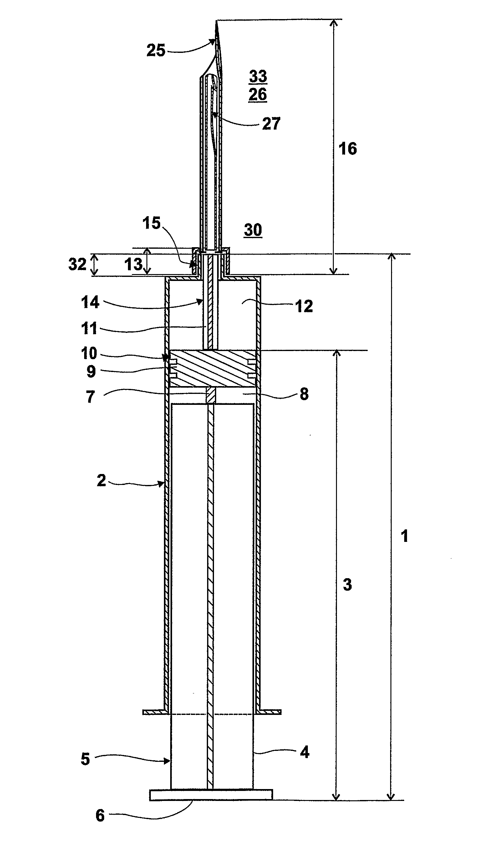
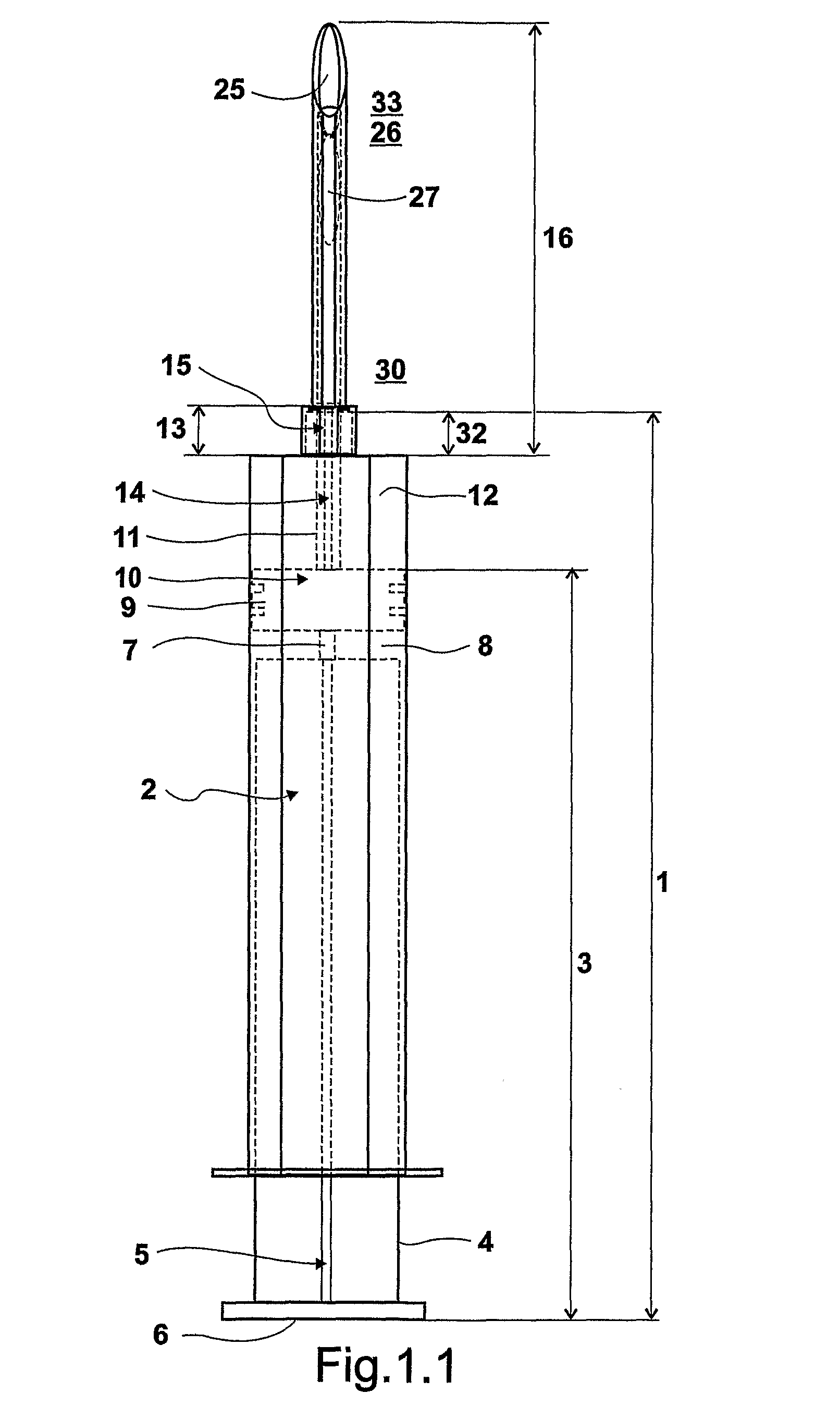
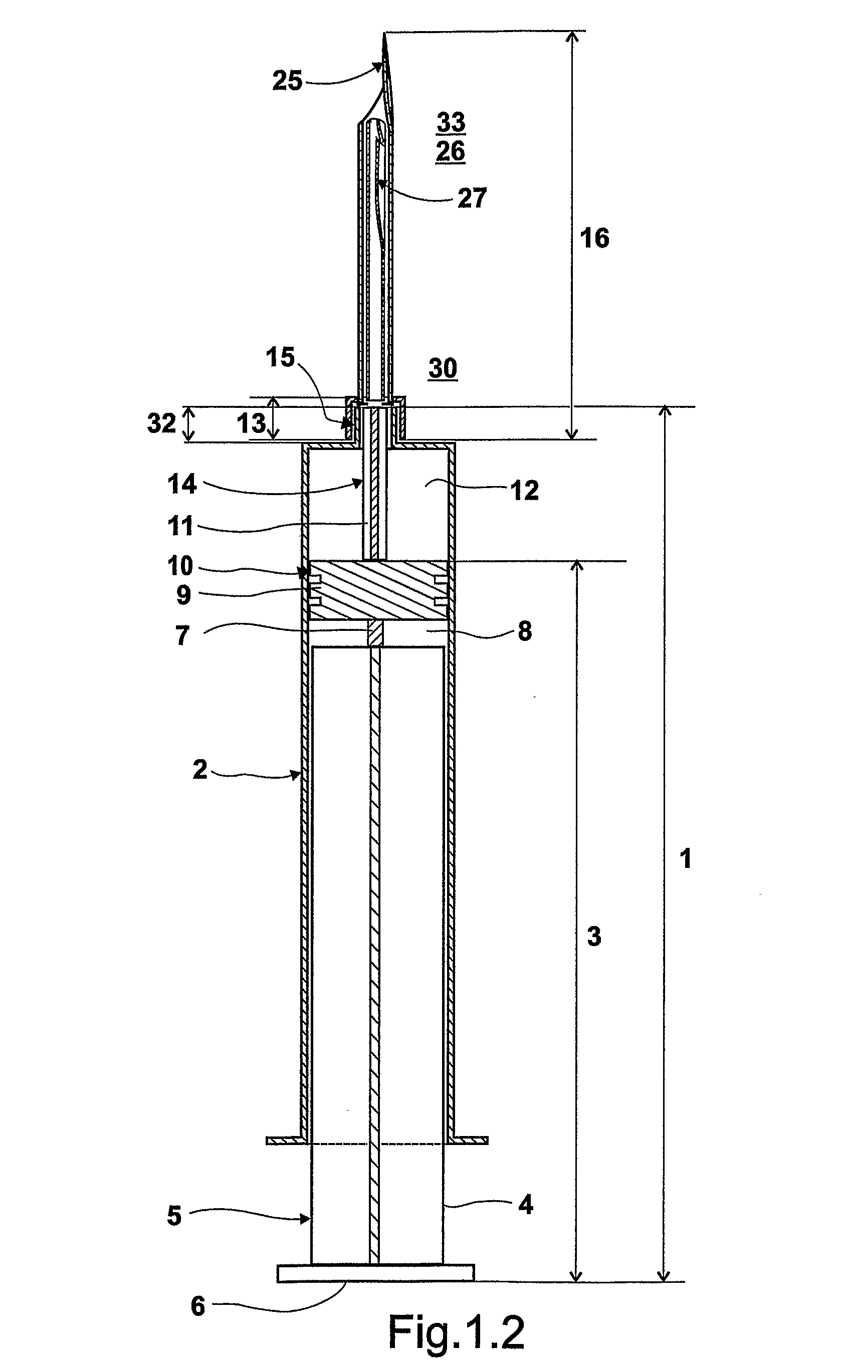
[0006]FIG. 1.1 is a complete view of the needle system and syringe. Referring now to the drawing in FIG. 1.2 which presents a hypodermic syringe generally represented at 1. Unlike a typical tubular syringe, the syringe has a flattened surface along the length represented at 2. The Plunger Rod is generally indicated at 3, the Plunger Rod shall have a normal arm at 4 and a Flattened arm at 5, to align with the flattened surface of the Tubular Syringe at 2. The Plunger Rod has a thumb rest at 6.

[0007]The plunger arms extend into a plunger head support at 7. There is a cavity 8 between the plunger arms and the plunger head 9. The plunger head 9 has a flattened surface 10 to align with the flattened surface of the syringe 2. From the Plunger Head 9 emerges Plunger Extension 11 into the syringe cavity 12. Plunger extension 11 extends to the Needle Mouth that is generally indicated at 13.

[0008]The Plunger Extension 11 has a flattened surface 14 along the length. The Plunger Extension can b...


PUM


Abstract

A safety needle locking device, which may be used with a syringe, consisting of a Blunting Member (19). The Needle (16) has a Needle Curvature (25) which allows locking of the Blunting Member (19) within the needle with the indent (27). The blunting member also has a Puncture Tip Protector (26) which allows for the Needle Tip (24) to be sheathed upon expulsion of the fluid. The needle is tubular with one surface flattened out. The Blunting Member is aligned within the needle. When the fluids are expelled the blunting member moves out, blocks the needle tip and locks inside the needle. Thus preventing reuse and needle stick injury. The syringe is flattened along one longitudinal surface to allow for alignment.

Description

INDUSTRIAL APPLICABILITY[0001]The present invention has been made to protect the health of medical and non-medical persons who face the potential risk of needle stick injury. Although syringes and needles have been widely used in the medical field or industry for over a hundred years, their potential hazardous nature and their implications on health care and other workers have only recently been studied. Safety-Engineered Medical Devices (SEMDs) are specially manufactured versions of these sharp and potentially injurious medical products, designed for safer use by medical professionals.[0002]The world market for SEMD's totaled an estimated $780 Million in the year 2001 alone and is projected to exceed to $1.6 billion by 2005, based on 20% predicted growth. There are approximately 800,000 to 1 Million exposures to blood borne pathogens in US every year due to needle stick injuries. Of which approximately 2% are HIV exposures resulting in 16,000 new infections. More than 20 diseases c...

Claims


Application Information

Patent Timeline
Patent Type & Authority Applications(United States)
IPC IPC(8): A61M5/50
CPCA61M5/158A61M2005/3212A61M5/321A61M5/3129
Inventor AGRAWAL, ARPITA
Owner AGRAWAL ARPITA
Why Eureka
Try Eureka