
Heat dissipation device

Inactive Publication Date: 2009-11-12
FU ZHUN PRECISION IND SHENZHEN +1
View PDF17 Cites 4 Cited by
  • Summary
  • Abstract
  • Description
  • Claims
  • Application Information

AI Technical Summary

Benefits of technology

[0005]Often, a heat dissipation device is attached to a top surface of a CPU in order to dissipate heat generated therefrom. A typical heat dissipation device includes a heat sink attached to the CPU. The heat sink includes a plurality of fins. A fan is mounted on top of the fins of the heat sink. It is known that the fan generates vibration when operating. The fins, on which the fan is mounted by a clip, will vibrate sympathetically with the fan, whereby considerable noise is generated during the operation of the heat dissipation device.

Problems solved by technology

Electronic components, such as central processing units (CPUs), generate large amounts of heat during normal operation.
If the heat is not properly dissipated, it can adversely affect operational stability of the electronic components and damage associated electronic devices.
It is known that the fan generates vibration when operating.
The fins, on which the fan is mounted by a clip, will vibrate sympathetically with the fan, whereby considerable noise is generated during the operation of the heat dissipation device.

Method used


Image

  • Heat dissipation device
  • Heat dissipation device
  • Heat dissipation device

Examples


Embodiment Construction

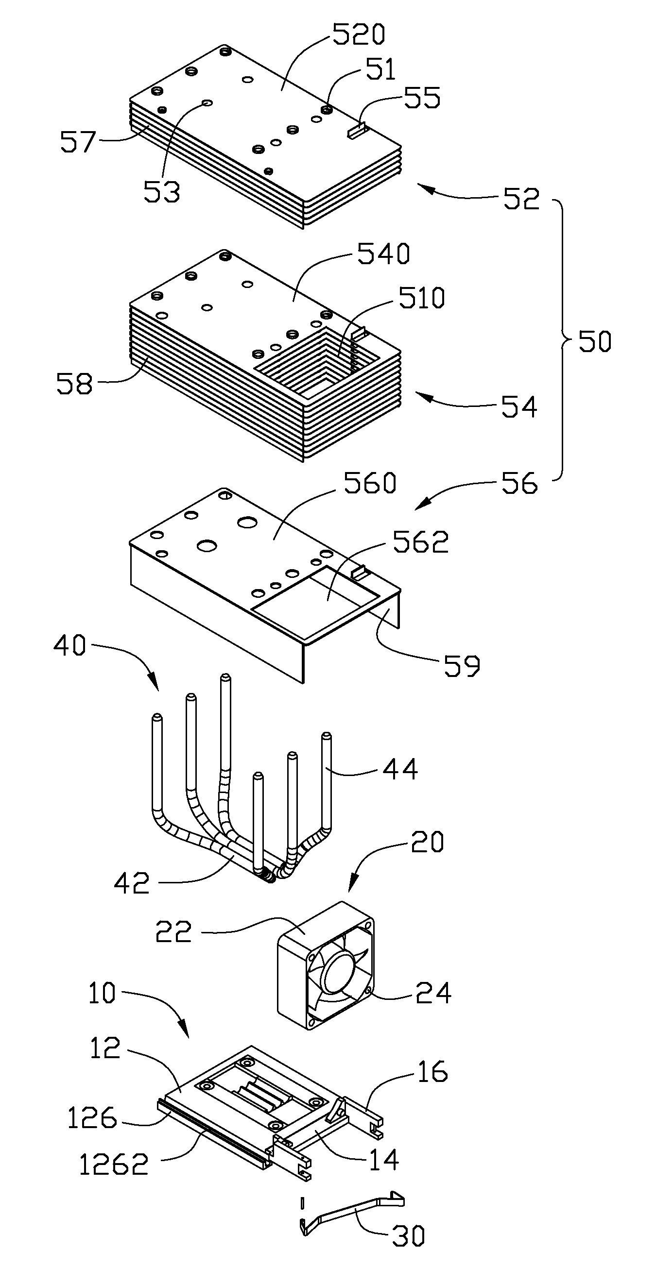
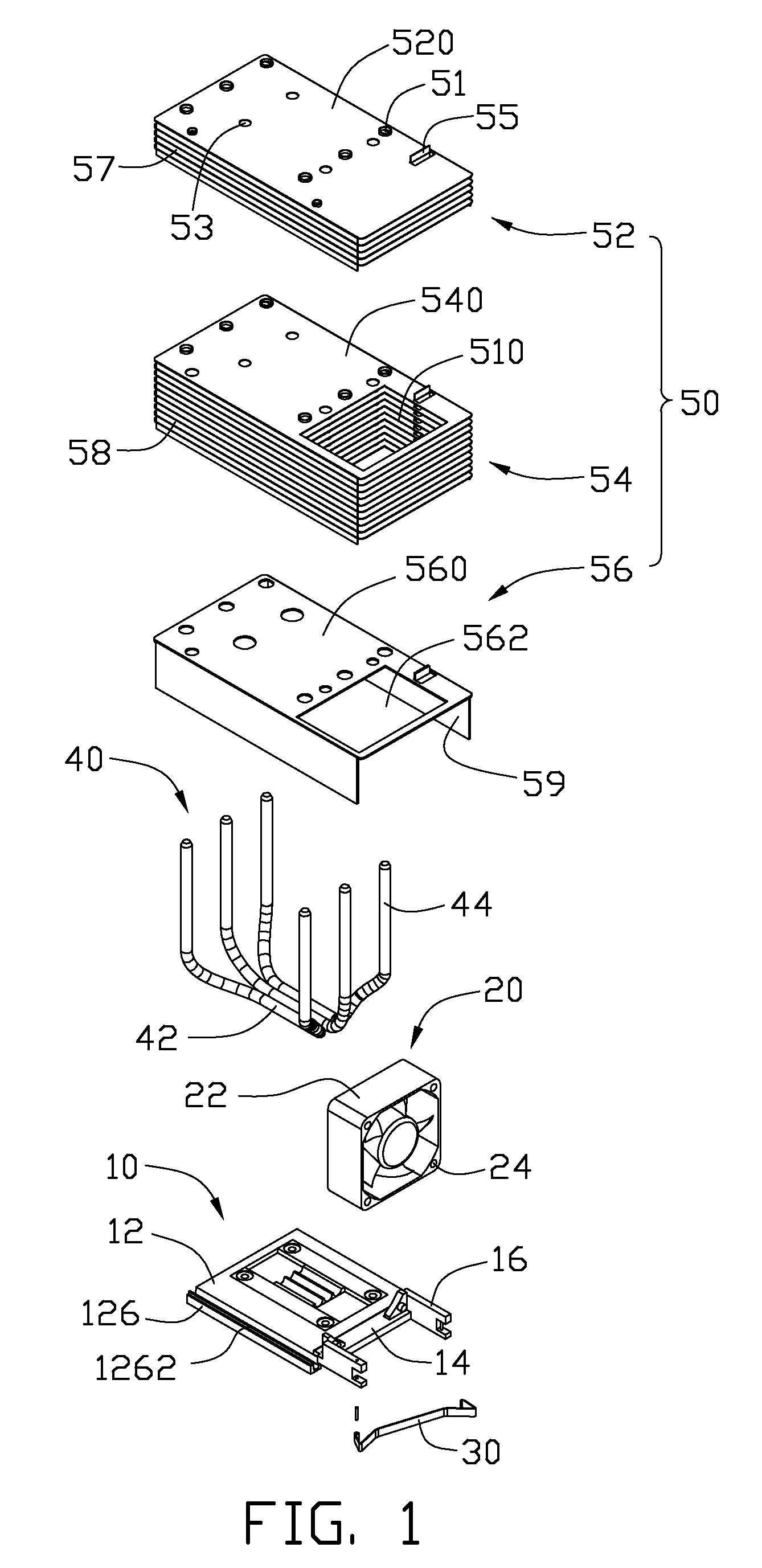
[0012]Referring to FIG. 1, a heat dissipation device in accordance with an embodiment of the disclosure dissipates heat generated by an electronic component (not shown), such as a CPU. The heat dissipation device comprises a substrate 10 attached to the electronic component, a fan 20 fixed on the substrate 10 by a clip 30, three heat pipes 40 and a fin assembly 50 located on the substrate 10.

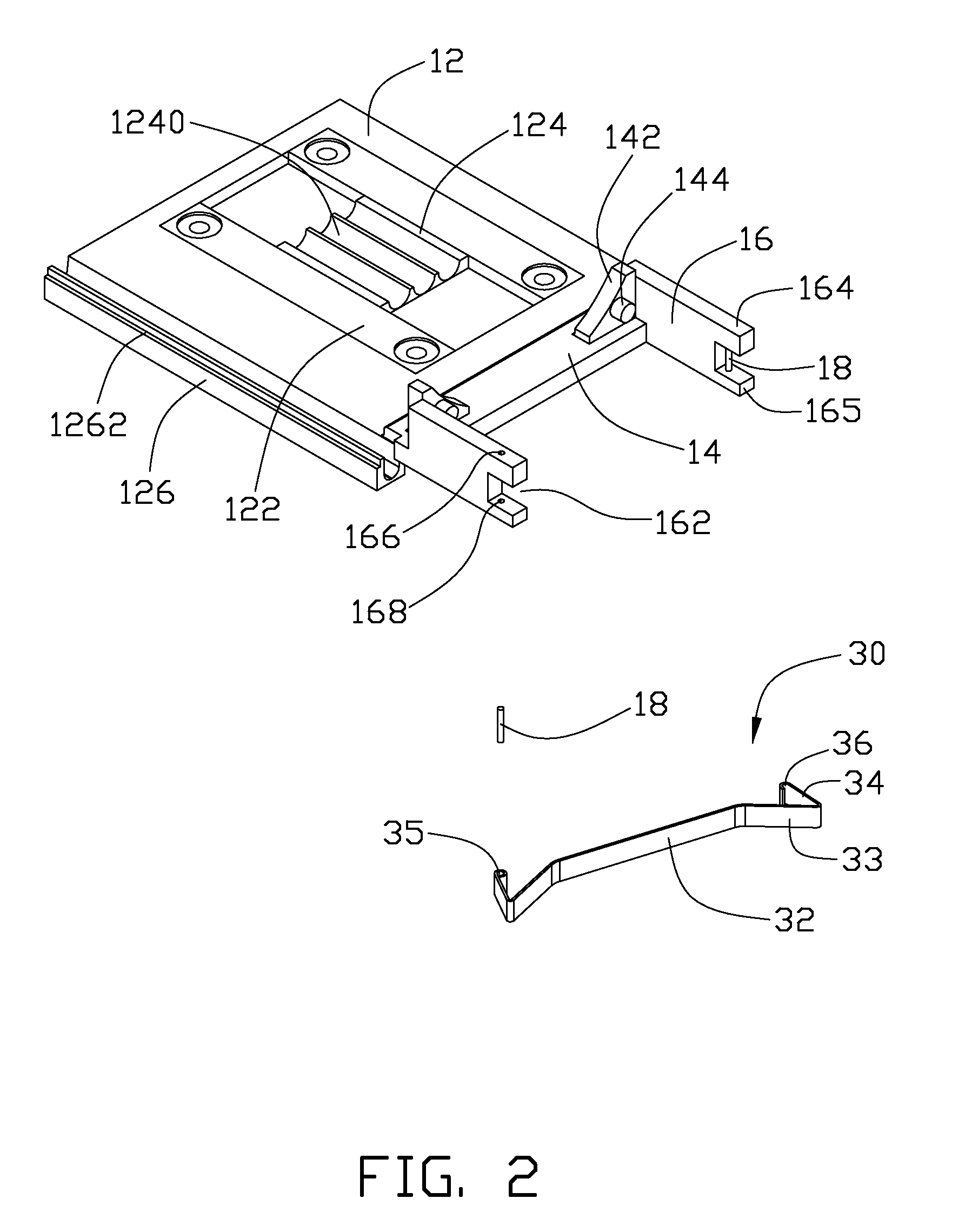
[0013]Also referring to FIG. 2, the substrate 10 comprises a substantially square plate 12, two parallel and spaced panels 16 and a rectangular plate 14 positioned therebetween, all extending from the front end of the square plate 12.

[0014]The square plate 12 defines a rectangular hatch (not labeled) receiving a base 122 therein. The base 122 is near a right side and far from a left side of the square plate 12. The base 122 comprises a center core 124, with a bottom surface thereof attached to the electronic component. Three grooves 1240 are defined in a top surface of the center core 124 receiv...


PUM


Abstract

A heat dissipation device includes a substrate, a fin assembly located on the substrate, a plurality of heat pipes connecting the substrate and the fin assembly, and a fan fixed on the substrate by a clip. The fin assembly includes a first fin unit, a second fin unit, and a third fin unit. The third fin unit is located on the substrate, the second fin unit is located on the third fin unit, and the first fin unit is located on the first fin unit. A receiving space is defined in the second and third fin unit. The fan is received in the receiving space and spaced apart from the fin assembly.

Description

BACKGROUND OF THE INVENTION [0001]1. Field of the Invention[0002]The present disclosure relates to heat dissipation and, more particularly, to a heat dissipation device having a fan fixed on a substrate thereof.[0003]2. Description of Related Art[0004]Electronic components, such as central processing units (CPUs), generate large amounts of heat during normal operation. If the heat is not properly dissipated, it can adversely affect operational stability of the electronic components and damage associated electronic devices.[0005]Often, a heat dissipation device is attached to a top surface of a CPU in order to dissipate heat generated therefrom. A typical heat dissipation device includes a heat sink attached to the CPU. The heat sink includes a plurality of fins. A fan is mounted on top of the fins of the heat sink. It is known that the fan generates vibration when operating. The fins, on which the fan is mounted by a clip, will vibrate sympathetically with the fan, whereby considera...

Claims


Application Information

Patent Timeline
IPC IPC(8): F28D15/00F28D21/00
CPCF28D15/0266F28F1/32H01L23/427H01L23/467H01L2924/0002H01L2924/00
Inventor LI, WEIWU, YI-QIANGCHEN, CHUN-CHI
Owner FU ZHUN PRECISION IND SHENZHEN
Learn More