Method and system of hydraulic control line connection

a technology of hydraulic control line and connection method, which is applied in the direction of sealing/packing, drilling pipes, and well accessories, etc., can solve the problems of increased risk and associated cost of inventory storage, and achieve the effect of preventing contamination of the fluid contained

Active Publication Date: 2009-11-12
SCHLUMBERGER TECH CORP
View PDF5 Cites 10 Cited by
  • Summary
  • Abstract
  • Description
  • Claims
  • Application Information

AI Technical Summary

Benefits of technology

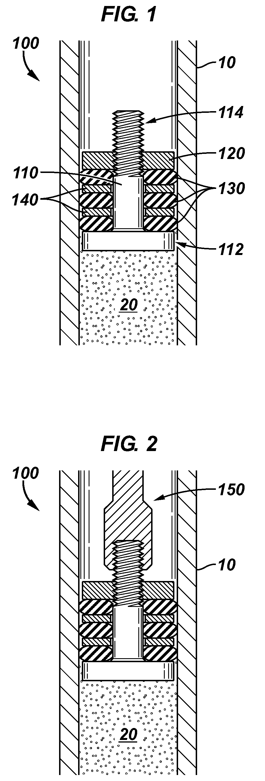
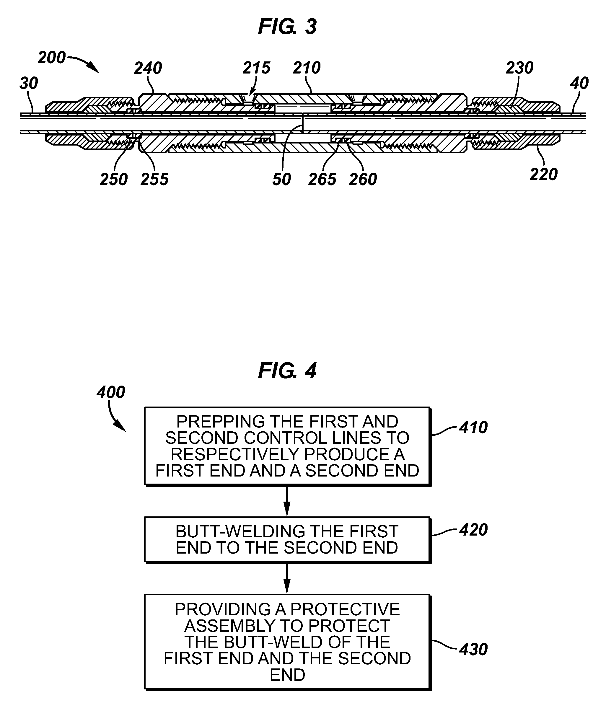
[0007]In accordance with an embodiment of the present invention, a method of coupling a first control line to a second control line may comprise prepping the first and second control lines to respectively produce a first end and a second end, such as through facing. A plug may be inserted during the prepping step in order to prevent contamination of the fluid contained in the control line. Another step in the method may be butt-welding the first end to the second end to produce a splice. Additionally, the method may include providing a protective assembly to protect the splice between the first end and the second end.

Problems solved by technology

However, this involves an increased risk due at least in part to the introduction of two potential leak paths via the two metal-to-metal primary seals per splice connection, along with the associated cost of storage of an inventory of couplings that must be made to relatively strict tolerances.

Method used


Image

  • Method and system of hydraulic control line connection
  • Method and system of hydraulic control line connection
  • Method and system of hydraulic control line connection

Examples


Embodiment Construction

[0019]In the following description, numerous details are set forth to provide an understanding of the present invention. However, it will be understood by those of ordinary skill in the art that the present invention may be practiced without these details and that numerous variations or modifications from the described embodiments may be possible. In the specification and appended claims: the terms “connect”, “connection”, “connected”, “in connection with”, “connecting”, “couple”, “coupled”, “coupled with”, and “coupling” are used to mean “in direct connection with” or “in connection with via another element”; and the term “set” is used to mean “one element” or “more than one element”. As used herein, the terms “up” and “down”, “upper” and “lower”, “upwardly” and downwardly”, “upstream” and “downstream”; “above” and “below”; and other like terms indicating relative positions above or below a given point or element are used in this description to more clearly describe some embodiment...


PUM

PropertyMeasurementUnit
non-metallicaaaaaaaaaa
circumferenceaaaaaaaaaa
diametersaaaaaaaaaa

Abstract

A method of coupling a first control line to a second control line is provided comprising the steps of prepping the first and second control lines to respectively produce a first end and a second end. Prepping may comprise inserting a plug assembly into at least one of the first or second ends prior to facing the end containing the plug assembly. The method may further include butt-welding the first end to the second end to form a splice and providing a protective assembly to cover the splice. The plug assembly may comprise a plug member, a seal, and an end piece to couple the seal to the plug member, in some embodiments. In other embodiments, the plug assembly may comprise a plug member and a seal coupled to the plug member.

Description

RELATED APPLICATIONS[0001]This application claims the benefit of U.S. Provisional Application No. 61 / 051,949, titled “METHOD AND SYSTEM OF HYDRAULIC CONTROL LINE CONNECTION,” filed May 9, 2008, the contents of which are herein incorporated by reference.BACKGROUND[0002]1. Field of the Invention[0003]Embodiments of the present invention relate generally to methods of making tubing connections and more particularly to methods of making connections between hydraulic control lines such as those used in downhole applications.[0004]2. Description of the Related Art[0005]The following descriptions and examples are not admitted to be prior art by virtue of their inclusion in this section.[0006]Hydraulic fluid is widely used to communicate with and / or actuate various downhole tools and components. One means of conveying the hydraulic fluid to the tools and components is through the use of various diameters (¼″, ½″ etc) of hydraulic control lines selected according to the particular applicatio...

Claims


Application Information

Patent Timeline
Patent Type & Authority Applications(United States)
IPC IPC(8): E21B17/04E21B33/12
CPCE21B17/02Y10T29/49002E21B17/1035E21B17/04
Inventor GUVEN, OGUZHAN
Owner SCHLUMBERGER TECH CORP
Why Eureka
Try Eureka