Enclosure member

a technology of enclosing member and enclosing body, which is applied in the field of enclosing member, can solve the problems of compromising the performance of the chain, and achieve the effect of improving the stability of the container

Inactive Publication Date: 2009-11-12
PENNINE INDAL EQUIP
View PDF0 Cites 16 Cited by
  • Summary
  • Abstract
  • Description
  • Claims
  • Application Information

AI Technical Summary

Benefits of technology

[0022]By enclosing the first end and second end of each of the first and second elongate pins in the deep non-tapered counterbore of the first and second enclosure members, the tendency for a rounded pin head exposed beyond the edge of the conveyor surface to “catch” or be sheared off is eliminated but there is sufficient head clearance to ensure that performance is not compromised under circumstances in which there is thermal expansion (e.g., of the link plates) or material deformation. In particular, the deep counterbore ensures that at temperatures in excess of 120° C., locking and tightening in the chain do not occur. Equally when a user requires a top face of the chain to be ground for improved container stability, the deep counterbore serves to ensure that there is sufficient head clearance to accommodate the cumulative effect of folding on the corner of each link plate caused by grinding.

Problems solved by technology

However in certain circumstances, the lower head clearance compromises the performance of the chain.

Method used


Image

  • Enclosure member
  • Enclosure member
  • Enclosure member

Examples


first embodiment

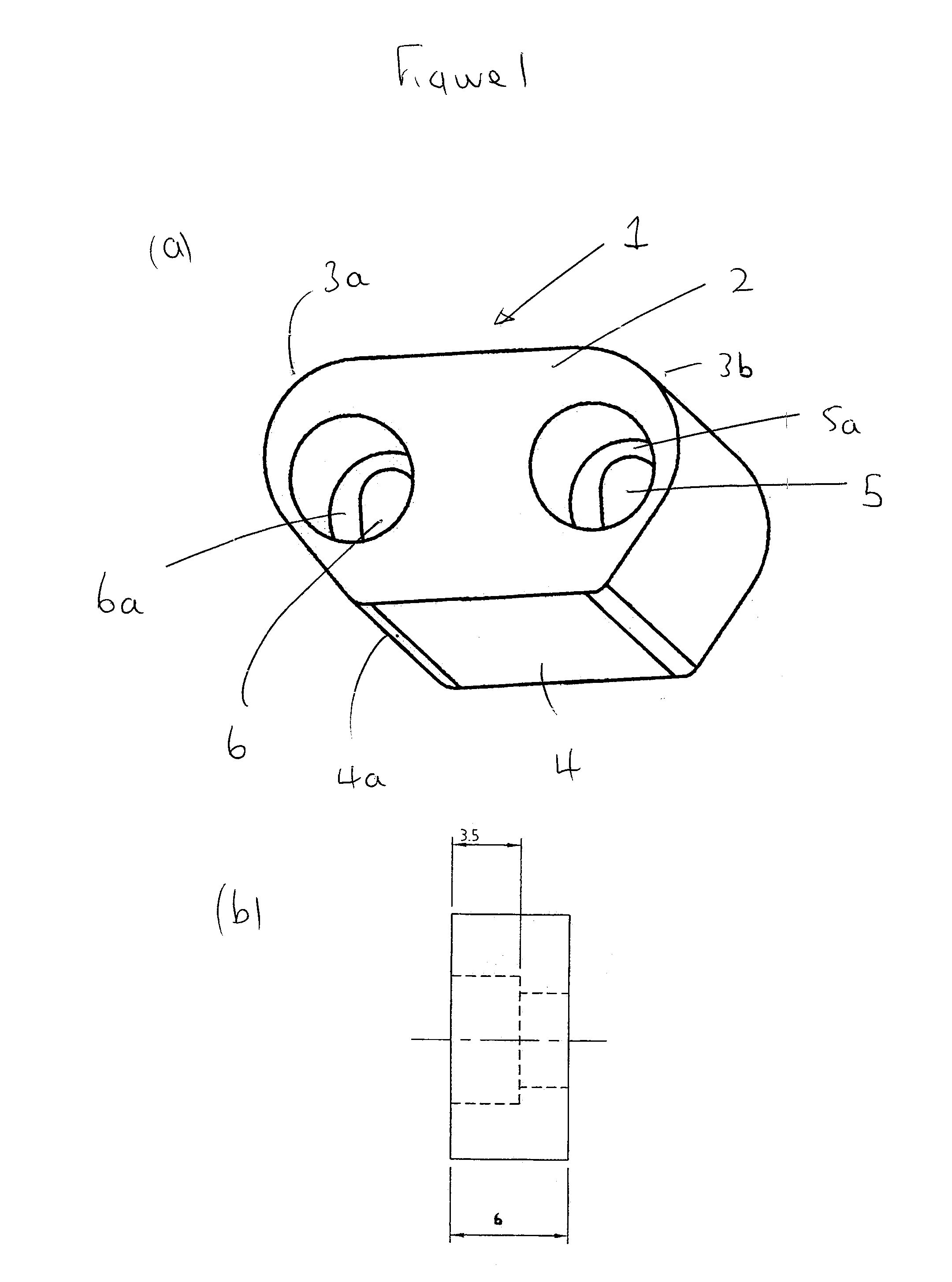
[0061]FIG. 1 illustrates the enclosure member of the invention designated generally by reference numeral 1. The enclosure member 1 is used in multi-guide conveyor chains and has a thickness of 6 mm. The enclosure member 1 comprises a trapezoidal main body 2 having a long side 3 parallel to a closed short side 4. The corners 3a and 3b of the long side 3 are rounded off (and to a lesser extent so are the corners 4a and 4b of the short side 4). The main body 2 defines a first non-circular aperture 5 and a second non-circular aperture 6, each of which are elliptical and provided with a cylindrical counterbore 5a and 6a respectively. The counterbores 5a and 6a are non-tapered and have a depth of 3.5 mm.

second embodiment

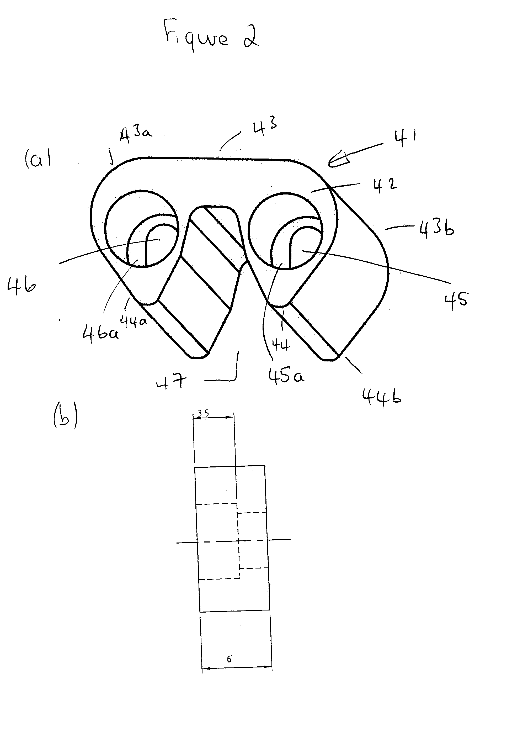
[0062]FIG. 2 illustrates the enclosure member of the invention designated generally by reference numeral 41. The enclosure member 41 is used in centre guide chains and has a thickness of 6 mm. The enclosure member 41 comprises a trapezoidal main body 42 having a long side 43 parallel to an open short side 44. The open short side is defined by a deep U-shaped cut-away portion 47. The corners 43a and 43b of the long side 43 are rounded off (and to a lesser extent so are the corners 44a and 44b of the short side 44). The main body 42 defines a first non-circular aperture 45 and a second non-circular aperture 46, each of which are elliptical and provided with a cylindrical counterbore 45a and 46a respectively. The counterbores 45a and 46a are non-tapered and have a depth of 3.5 mm.

third embodiment

[0063]FIG. 3 illustrates the enclosure member of the invention designated generally by reference numeral 31. The enclosure member 31 is used in side guide chains and has a thickness of 6 mm. The enclosure member 31 comprises a trapezoidal main body 32 having a long side 33 parallel to a closed short side 34. The corners 33a and 33b of the long side 33 are rounded off (and to a lesser extent so are the corners 34a and 34b of the short side 34). The rear face of the main body 32 is partially recessed with a substantially U-shaped recess 432. The main body 32 defines a first non-circular aperture 35 and a second non-circular aperture 36, each of which are elliptical and provided with a cylindrical counterbore 35a and 36a respectively. The counterbores 35a and 36a are non-tapered and have a depth of 3.5 mm.

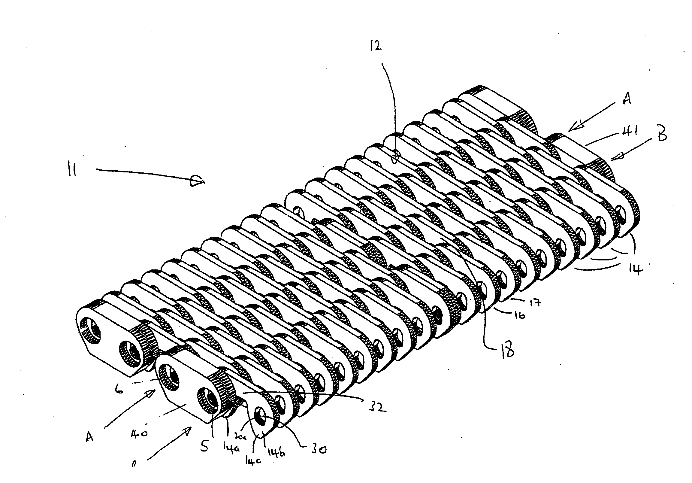
[0064]FIG. 4 illustrates in partial view an embodiment of the multi-link conveyor chain of the invention designated generally by reference numeral 11. For the sake of clarity, the elo...


PUM


Abstract

The present invention relates to a multi-link conveyor chain which may be used (for example) in the glass industry and to an enclosure member for use in the multi-link conveyor chain.

Description

BACKGROUND OF THE INVENTION[0001]1. Field of the Invention[0002]The present invention relates to a multi-link conveyor chain which may be used (for example) in the glass industry and to an enclosure member for use in the multi-link conveyor chain.[0003]2. State of the Art[0004]Multi-link conveyor chains are in widespread use in the glass industry for transporting glass products between processing stations. For example, a multi-link conveyor chain which is typically 100 feet long may be used to transport blown glass from a blowing station to an annealing station. In one conventional multi-link conveyor chain, there is a plurality of parallel spaced apart elongate pins having an oval-shaped cross-section. Mounted on adjacent elongate pins are a series of link plates spaced apart along the pin by a plurality of washers, each link plate comprising a first and a second link. Each of the first and second link is capable of engaging a drive sprocket and has an oval-shaped aperture for rece...

Claims


Application Information

Patent Timeline
Patent Type & Authority Applications(United States)
IPC IPC(8): B65G17/06
CPCB65G2207/12B65G17/08
Inventor MARSHALL, CHRISTOPHER
Owner PENNINE INDAL EQUIP
Why Eureka
Try Eureka