Vehicle occupant restraint system

Active Publication Date: 2009-11-12
NISSAN MOTOR CO LTD +1
View PDF17 Cites 7 Cited by
  • Summary
  • Abstract
  • Description
  • Claims
  • Application Information

AI Technical Summary

Benefits of technology

[0006]In the above vehicle occupant restraint system, a frictional force generated by direct contact between the lower face of the upper airbag and the upper face of the lower airbag prevents the upper and lower airbags from being displaced from each other in the vehicle front-rear

Problems solved by technology

However, in the cases where an inertial force acting on the vehicle occupant during breaking of the vehicle is large and where forces of

Method used


Image

  • Vehicle occupant restraint system
  • Vehicle occupant restraint system
  • Vehicle occupant restraint system

Examples


Example

First Embodiment

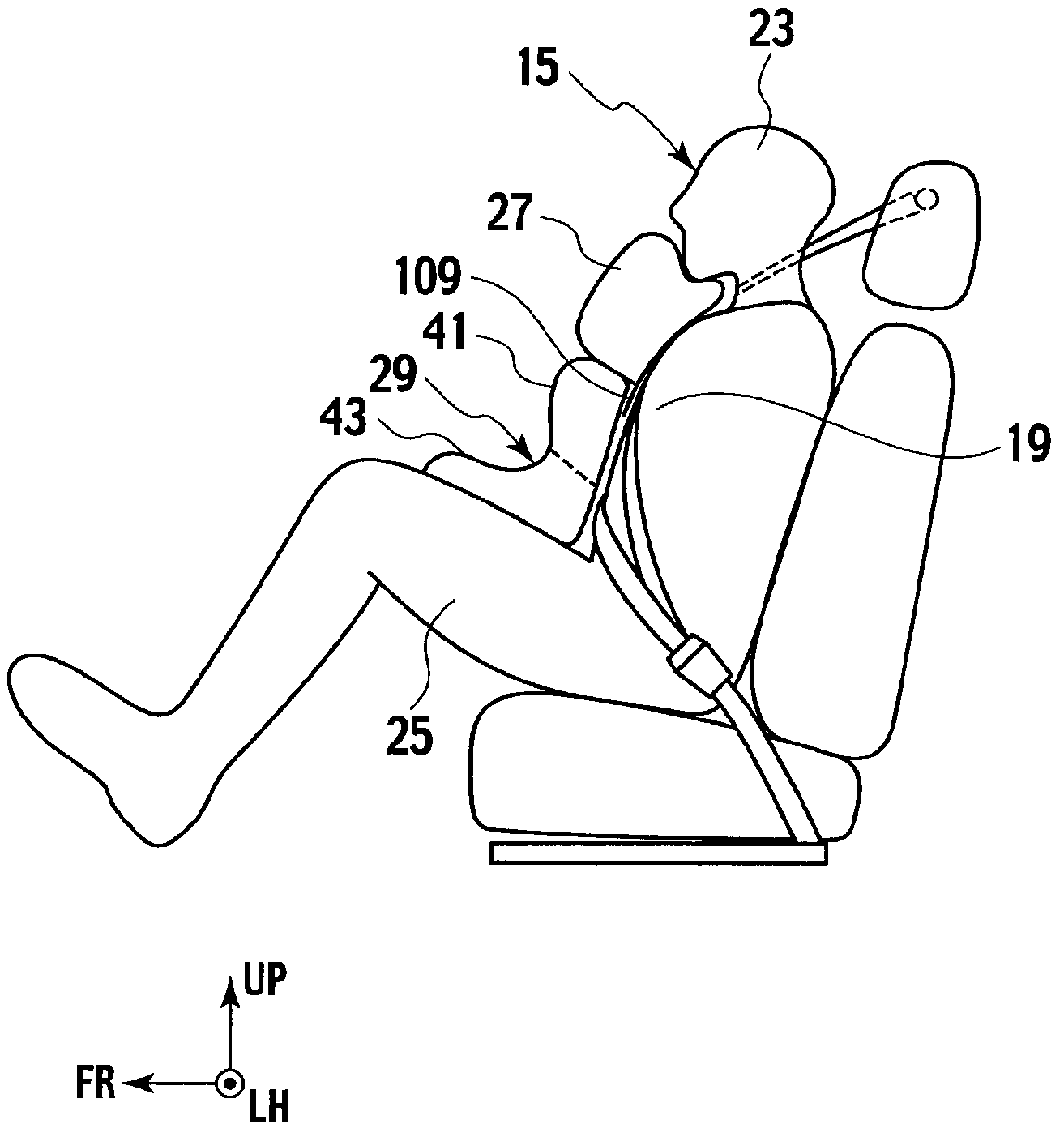
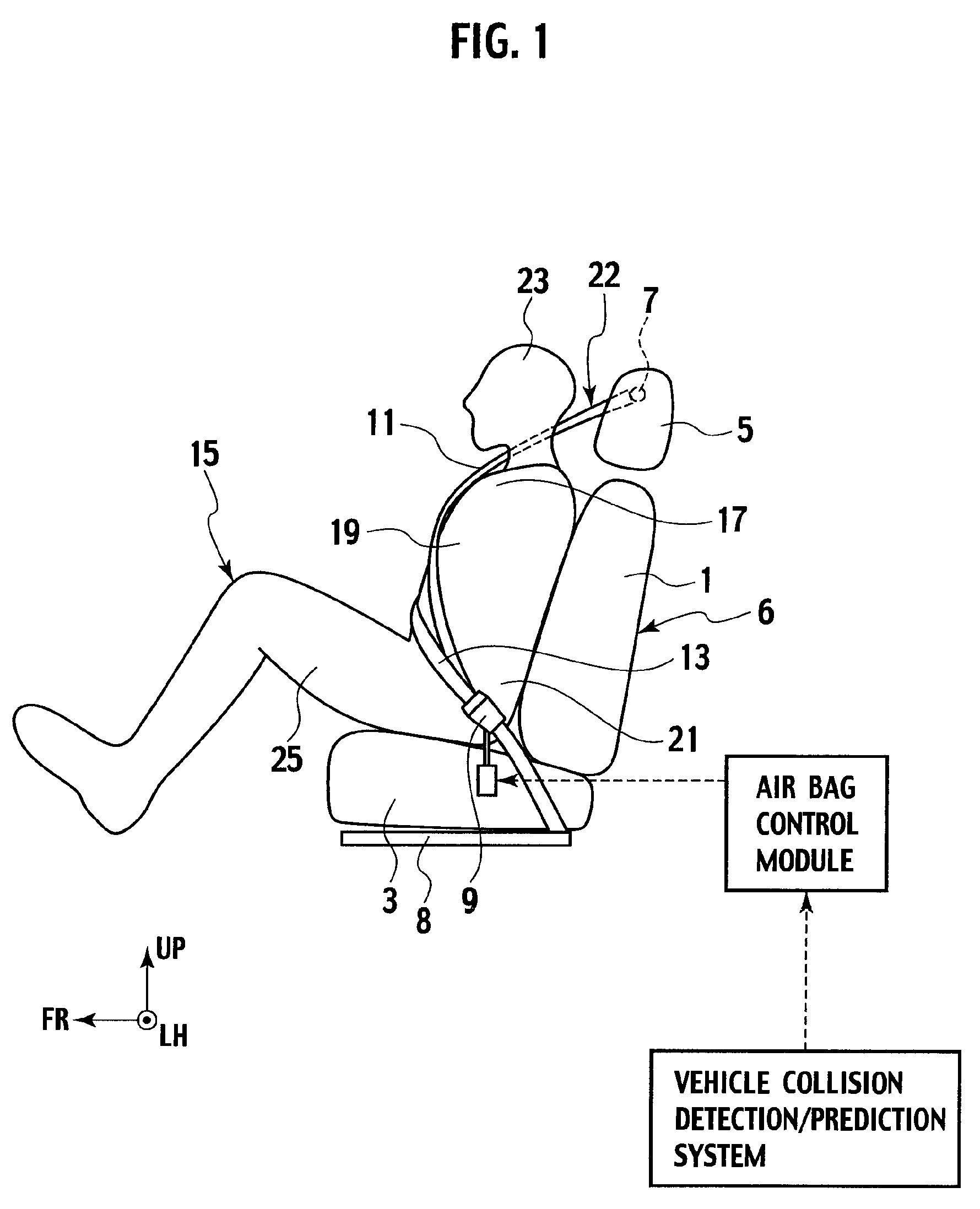
[0021]A vehicle occupant restraint system according to a first embodiment of the present invention will be described with reference to FIG. 1. Note that, although a vehicle occupant restraint system arranged for a right-side rear seat of a vehicle will be described as an example in this embodiment, the system can be applied to seats in other positions.

[0022]Additionally, in the present invention, the upper airbag and the lower airbag are deployed when a vehicle collision detection / prediction system “detects” or “predicts” a collision of the vehicle. Here, the “detection” or “prediction” is not limited to a case where a collision load inputted to the vehicle is detected, but broadly includes, for example, such cases as where a running speed decrease of the vehicle is detected, where a situation that the vehicle is expected to come into contact with an obstacle is detected, and where a collision with an obstacle is predicted by external environment detection means form...

Example

Second Embodiment

[0051]Next, a vehicle occupant restraint system according to a second embodiment of the present invention will be described. The same reference numerals are attached to the same sections as those of the above described first embodiment, and description thereof will be omitted.

[0052]FIG. 7 is a front view of an upper airbag according to the second embodiment of the present invention, which is provided with a second movement restraining portion.

[0053]This upper airbag 113 is formed of an upper airbag main body portion 115, and the second movement restraining portion 117 which is a linear member joining the end portions 105 and 107 of the concaved section 103 of the upper airbag main body portion 115. To the second movement restraining portion 117, any one of various linear members can be applied as long as the one is an inelastic string, strip, and the like. Additionally, both ends of the second movement restraining portion 117 can be fixed to the upper airbag main bo...

Example

Third Embodiment

[0056]Next, a vehicle occupant restraint system according to a third embodiment of the present invention will be described. The same reference numerals are attached to the same sections as those of the above described first and second embodiments, and description thereof will be omitted.

[0057]FIG. 8 is a front view showing an upper airbag according to a third embodiment of the present invention, which is yet to be deployed, and FIG. 9 is a side view of a state where the upper airbag shown in FIG. 8 and a lower airbag are deployed. As shown in FIG. 8, the upper airbag 119 is integrally formed of: an upper airbag main body portion 121; the first movement restraining portion 109 provided to a lower side of the upper airbag main body portion 121; and an extended portion 123 provided on top of the upper airbag main body portion 121.

[0058]The extended portion 123 is a substantially trapezoidal remainder of at least any one of two front-side and back-side sheet materials fo...


PUM


Abstract

A vehicle occupant restraint system including: a seatbelt device including a shoulder belt portion restraining a part of a vehicle occupant from one of shoulders to a chest, and a lap belt portion restraining a waist of the vehicle occupant; an upper airbag provided in the shoulder belt portion, and configured to be deployed forward from the shoulder belt portion; a lower airbag provided in the lap belt portion, and configured to be deployed forward from the lap belt portion, the deployed upper and lower airbags coming into contact with each other in a vertical direction; and a movement restraining portion restraining relative movement of the deployed upper and lower airbags in a front-rear direction, extending downward from a lower side of the deployed upper airbag, and positioned in the rear of the deployed lower airbag.

Description

BACKGROUND OF THE INVENTION[0001]1. Field of the Invention[0002]The present invention relates to a vehicle occupant restraint system for protecting an occupant of a vehicle when the vehicle detects or predicts a collision.[0003]2. Description of the Related Art[0004]Japanese Patent Application Laid-Open Publication No. 2006-160062 discloses a vehicle occupant restraint system which has airbags installed inside a seatbelt and is configured to protect an occupant of a vehicle by deploying the airbags when a front collision of the vehicle occurs.[0005]In the above system, an upper airbag and a lower airbag are respectively installed inside a shoulder belt portion and a lap belt portion which form the seatbelt. Additionally, when a collision of the vehicle occurs, the upper and lower airbags are prevented from being displaced from each other in a front-rear direction of the vehicle by individually deploying the upper and lower airbags so that a lower face of the upper airbag can come in...

Claims


Application Information

Patent Timeline
IPC IPC(8): B60R21/20B60R21/18B60R21/231B60R22/28
CPCB60R21/231B60R21/18B60R22/14B60R21/16
Inventor AZUMA, SEIJIOOTA, KOUICHIOKAMOTO, HIDEAKI
Owner NISSAN MOTOR CO LTD
Why Eureka
Try Eureka