Wind turbine generator system

Inactive Publication Date: 2009-11-12
HITACHI LTD
View PDF3 Cites 51 Cited by
  • Summary
  • Abstract
  • Description
  • Claims
  • Application Information

AI Technical Summary

Benefits of technology

[0009]An aspect of the present invention provides a wind turbine generator system comprising: an AC-excited generator, including a stator to be connected to a grid and a rotor coupled to a turbine for rotating the rotor, configured to supply a power to the grid; a converter unit including: an AC exciting converter, including a first DC part, configured to perform power conversion to AC-excite the rotor; and a grid side converter, connected to the stator and to be connected to the grid, including a second DC part connected to the first DC part, configured to perform power conversion to control a DC voltage; a s

Problems solved by technology

However, when a voltage drop in a grid occurs due to an earth fault, the AC-excited generator tends to supply a power to the place where the earth fault

Method used


Image

  • Wind turbine generator system
  • Wind turbine generator system
  • Wind turbine generator system

Examples


first embodiment

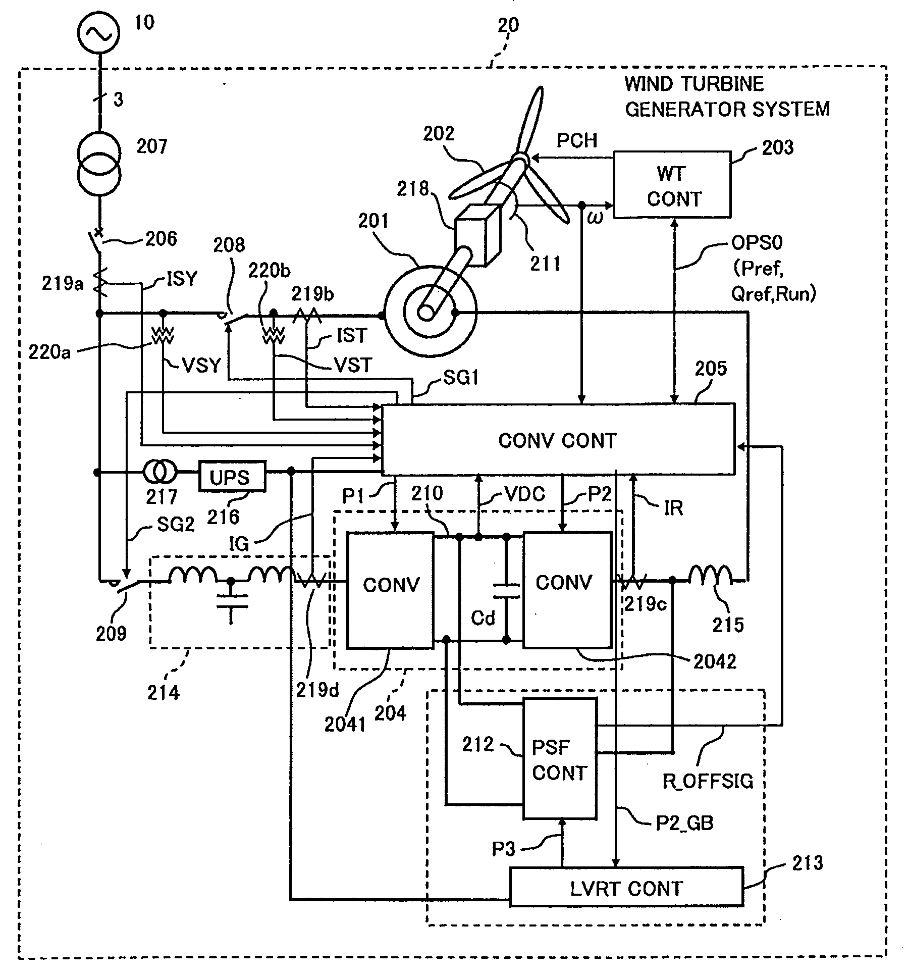
[0039]With reference to FIG. 1 (single wire circuit diagram) will be described a first embodiment of a wind turbine generator system according to the present invention.

[0040]A wind turbine generator 20 is connected to a grid 10 through transmission lines. The wind turbine generator system 20 mainly includes an AC-excited generator (doubly-fed induction machine) 201, blades 202, a wind turbine controller 203, a converter unit 204, a converter controller 205, a power system failure response circuit 212, and a power system failure response circuit controller (LVRT CONT) 213.

[0041]The blades 202 are mechanically coupled to the rotor of the generator 201 through gears 218.

[0042]Rotor windings of the generator 201 are electrically connected to the converter unit 204. A stator of the generator 201 is electrically connected to the gird 10 through a breaker 206 and a transformer 207, etc.

[0043]The wind turbine controller 203 calculates operation command signals OPS0 such as detecting a wind ...

second embodiment

[0139]FIG. 14 shows a second embodiment of the present invention. A wind turbine generator system according to the second embodiment is different in that the converter controller 205 directly transmits a resistor connecting signal OPS2 to the power system failure response circuit controller 213. In the first embodiment, the ON status holding circuit 2124 in the power system failure response circuit 212 determines timing of connecting and disconnecting the resistor R2. In the second embodiment, the resistor connecting signal OPS2 outputted by the converter controller 205 determines timing of connecting and disconnecting the resistor R2.

[0140]FIG. 15 shows configuration of the converter controller 205. The converter controller according to the second embodiment is different from that according to the first embodiment shown in FIG. 1 is that the monitoring loop process CTL_WTCH2 generates and sends the resistor connecting signal OPS2 to the power system failure response circuit 212.

[01...

third embodiment

[0148]FIG. 19 shows the converter controller 205 according to a third embodiment. The converter controller 205 according to the third embodiment is different from that shown in FIG. 15 is in that an inverter (NOT) and an AND gate (AND) are added to make the excessive current detection signal P2_GB in a stop status of “0” to monitor an excessive current upon the power system failure in an operation status.

[0149]FIG. 20 shows a flowchart of control operation of the generator side converter 2042, which is different from that show in FIG. 18 in that the excessive current upon a power system failure is monitored in the operation mode. When the excessive current detection signal P2_GB=1, it is determined that there is no excessive current. Further, in the third embodiment, it is further monitored whether the grid voltage decreases and DC voltage increases. When it is detected that the grid voltage decreases and the DC voltage (Cd) increases, a process of connecting the resistors R2 and R3...


PUM


Abstract

In a wind turbine generator system including an AC exciting converter a grid side converter, and a controller configured to control the AC-exciting converter and the grid side converter, the controller operates a short-circuiting circuit when decrease in the grid voltage and increase in the DC voltage are detected.

Description

CROSS REFERENCE TO RELATED APPLICATIONS[0001]This application claims the foreign priority benefit under Title 35, United States Code, §119(a)-(d) of Japanese Patent Application No. 2008-122844, filed on May 9, 2008 in the Japan Patent Office, the disclosure of which is herein incorporated by reference in its entirety.BACKGROUND OF THE INVENTION[0002]1. Field of the Invention[0003]The present invention relates to a wind turbine generator system and particularly to a wind turbine generator system capable of protecting a converter connected to a rotor of an AC-excited generator from a voltage drop due to a power failure in a grid.[0004]2. Description of the Related Art[0005]An AC-excited generator (Doubly-Fed Induction Machine) in a power generating system can equalize in frequency a generated voltage at a stator to a grid by AC-exciting a rotor at a slip frequency (difference between the grid frequency and a rotational frequency). The variable exciting frequency of the rotor (slip fre...

Claims


Application Information

Patent Timeline
IPC IPC(8): F03D7/00F03D9/00
CPCF05B2270/10711F05B2270/337H02P9/007H02P9/10H02P2101/15H02P29/032H02P29/0241F03D9/255Y02E10/72Y02P80/10F03D7/0284
Inventor ICHINOSE, MASAYAFUTAMI, MOTOOSAKAI, HIROMITSU
Owner HITACHI LTD
Why Eureka
Try Eureka