Display Device

a display device and display technology, applied in the field of display devices, can solve the problems of reducing the display quality, increasing the power consumption according to the raised luminance, and requiring a massive amount of work to cope, so as to reduce the blurredness of moving images, suppress the effect of the luminance reduction and the increase of the power consumption

Inactive Publication Date: 2009-11-12
PANASONIC LIQUID CRYSTAL DISPLAY CO LTD +1
View PDF12 Cites 36 Cited by
  • Summary
  • Abstract
  • Description
  • Claims
  • Application Information

AI Technical Summary

Benefits of technology

[0022]According to an aspect of the present invention, the display device is arranged not to insert a black tone independently of the tones required by the external system but switch the minimum tone with the predetermined tone if the tones required by the external are laid on the lower tone side when an image is displayed. Hence, the display device operates to pseudoly display the tones required by the external system by switching the maximum tone with the predetermined tone if the tones required by the external system are laid on the higher tone side. The display device thus provides a capability of reducing the blurredness of a moving image as suppressing reduction of a luminance and a contrast and increase of power consumption required for light emission. That is, for the lower luminance (the lower tone side), the display device is easy to recognize the blurredness of the moving image. By inserting the minimum tone, therefore, the blurredness of the moving image is reduced. On the other hand, for the higher luminance (the higher tone side), the display device has difficulty in recognizing the blurredness of the moving image. By enhancing the lower tone to be inserted, therefore, the reduction of a luminance and a contrast is suppressed.
[0023]According to another aspect of the present invention, the display device provides a capability of reducing the blurredness of a moving image as suppressing degrade of a tone characteristic, increase of power consumption required for light emission and increase of a circuit like a frame memory in scale.

Problems solved by technology

However, it is known that the application of the foregoing technologies brings about the following disadvantages.
Conversely, the suppression of the circuit scale results in bringing about an error in the interpolation, thereby remarkably lowering the display quality.
This results in increasing the power consumption according to the raised luminance and requiring a massive work for coping with the heat caused by the rise of the luminance.
Further, the increase of an absolute value of light leakage on the black display also results in lowering the contrast.
Hence, this system does not offer a target tone characteristic (γ characteristic) of the display, thereby making the image quality degraded.
That means that this system merely makes the display frequency twice or more as fast and does not consider enhancement of the liquid crystal response speed.
Hence, this system makes the luminance lower and does not reach the target tone characteristic (γ characteristic), thereby making the image quality degraded.
Moreover, this system does not consider the respect of reducing the capacity of a frame memory that holds the display data.
This also means that the display device to which this system is applied has difficulty in lowering the manufacturing cost.

Method used


Image

  • Display Device
  • Display Device
  • Display Device

Examples


first embodiment

[0084]The embodiments of the present invention arranged in the case of driving one frame with two fields will be described with reference to FIGS. 1 to 12.

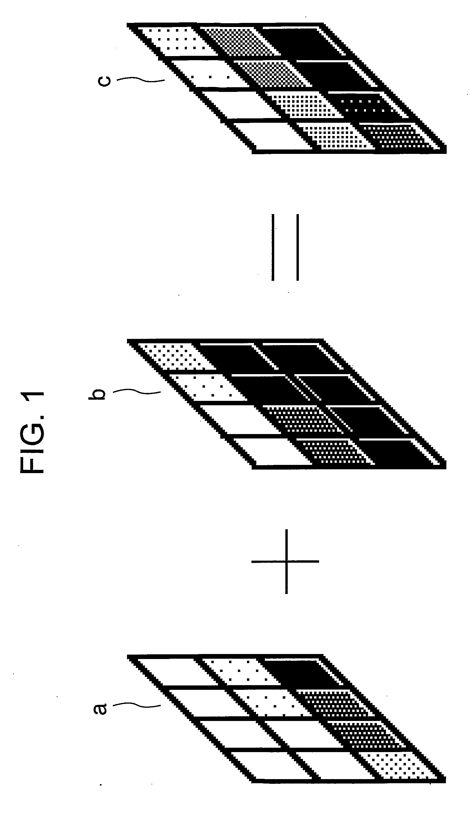
[0085]FIG. 1 shows the dynamic luminance and the visual luminance of each field of the display device consisting of 4×3 pixels. In FIG. 1, a denotes the dynamic luminance of the light field, b denotes the dynamic luminance of the dark field, and c denotes the visual luminance. In this embodiment, one frame is composed of two fields, and the data is displayed so that the dynamic luminance of one field is constantly lighter than or equal to the dynamic luminance of the other field with respect to any pixel. By repetitively switching these fields with each other, the target visual luminance can be obtained. Hence, with respect to any pixel, the relation of (dynamic luminance of the light field)≧(visual luminance)≧(dynamic luminance of dark field) is established. Instead of two fields for one frame, three or four fields for one frame ...

second embodiment

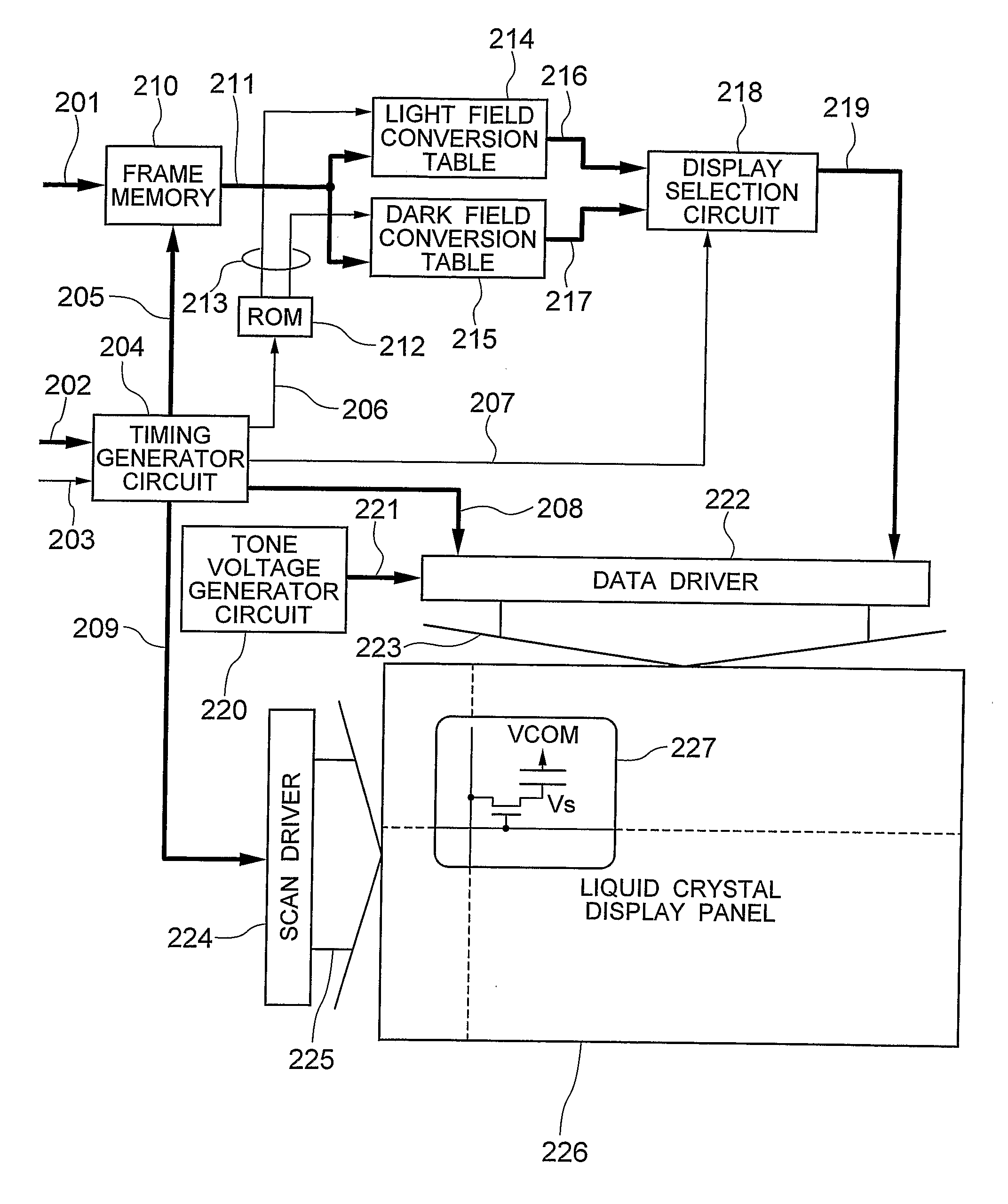
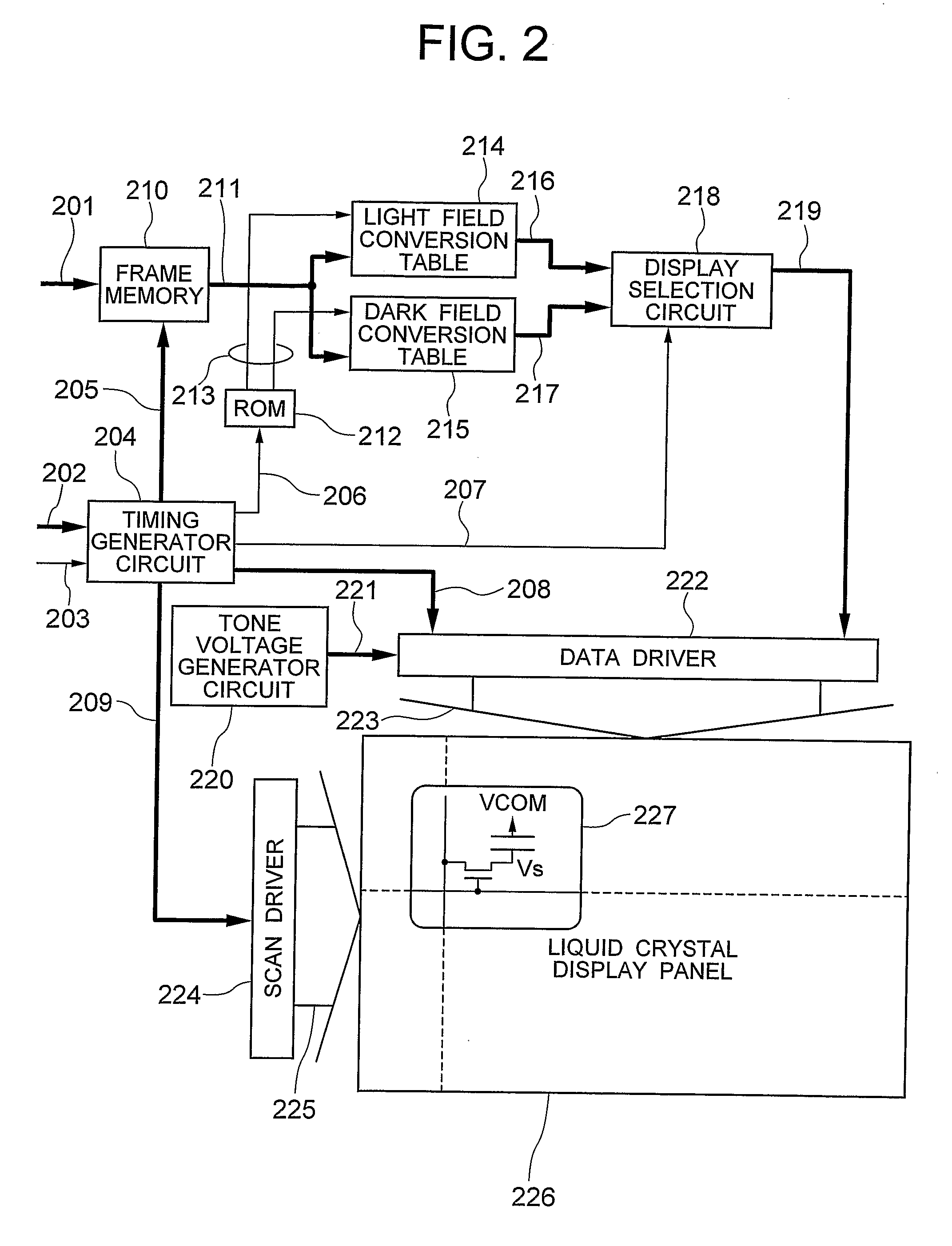
[0122]In turn, the description will be oriented to the different conversion algorithm of the display data about the light field and the dark field from that of the first embodiment through the use of the relation among the input display data 201, the light field display data 216 and the dark field display data 217 shown in FIG. 14.

[0123]In the field conversion described in the first embodiment, the conversion is carried out on the condition 1. On the other hand, the second embodiment is conditioned to realize the visual luminance corresponding with the input display data in the combination of the light and the dark fields, obtain the dynamic luminance that becomes as close to Tmin as possible as the dark field, and improve the moving image performance in the case of changing the tone into the white luminance (255 tones). This condition is referred to as the condition 2. To realize the condition 2, in this embodiment, the maximum value of the static luminance in the dark field is Tma...

third embodiment

[0125]In turn, the description will be oriented to the different conversion pattern from those of the first and the second embodiments through the use of the relation among the input display data 201, the light field display data 216 and the dark field display data 217 shown in FIG. 15.

[0126]In the meantime, as the typical frame frequencies of the broadcast wave are known the NTSC system, the PAL system and the SECAM system. In the NTSC system, the scan frequency of one screen (which is a field frequency of the so-called interlaced scan system, though it is different from the field frequency used in this specification) is about 60 Hz. When driven in two fields, the frequency of one field is about 120 Hz. On the other hand, the scan frequency of one screen in the PAL system or the SECOM system is about 50 Hz. When driven in two fields, the frequency of one field is about 100 Hz. As the dynamic luminance in the dark field is being lowered by using the conversion algorithm of the first...


PUM


Abstract

A one-frame interval is divided into a light field interval and a dark field interval. In the light field interval, the display data of high tones is displayed, while in the dark field interval, the display data of low tones is displayed. This divisional display makes it possible to pseudoly display the tones of the input display data. Then, in a case that the tones of the input display data is on the lower tone side, the display data of the dark field is set to the corresponding minimum tone with the minimum luminance, while in a case that the tone of the input display data is on the higher tone side, the display data of the light field is set to the corresponding maximum tone with the maximum luminance.

Description

INCORPORATION BY REFERENCE[0001]The present application claims priorities from Japanese applications JP2005-137986 filed on May 11, 2005, JP2005-219899 filed on Jul. 29, 2005, the contents of which are hereby incorporated by reference into this application.TECHNICAL FIELD[0002]The present invention relates to a hold-type display device such as a liquid crystal display device, an organic EL (Electro Luminescence) display and a LCOS (Liquid Crystal On Silicon) display, and more particularly to the display device which is suitable to displaying a moving image.BACKGROUND ART[0003]If a general display device is classified from a viewpoint of a moving-image display, the display device is roughly classified into an impulse response display and a hold response display. The impulse response display means a display type in which a luminance response is lowering immediately after scanning as is shown in the afterglow characteristic of a CRT. The hold response display means a display type in wh...

Claims


Application Information

Patent Timeline
Patent Type & Authority Applications(United States)
IPC IPC(8): G09G5/10
CPCG09G3/2025G09G2340/16G09G3/3614G09G3/3648G09G3/3677G09G2310/0216G09G2310/0218G09G2310/0254G09G2310/0267G09G2320/0204G09G2320/0219G09G2320/0247G09G2320/0252G09G2320/0261G09G2320/0276G09G2340/0435G09G3/2081G02F1/133G09G3/20G09G3/36H04N5/66
Inventor OISHI, YOSHIHISANITTA, HIROYUKIMARUYAMA, JUNICHIONO, KIKUO
Owner PANASONIC LIQUID CRYSTAL DISPLAY CO LTD
Why Eureka
Try Eureka