Light emitting device and a manufacturing method thereof

a technology of light emitting devices and manufacturing methods, which is applied in the direction of solid-state devices, lighting and heating apparatuses, spectral modifiers, etc., can solve the problems of low illumination efficiency of lighting apparatuses, increase the cost associated, and the manufacturing method, so as to achieve the effect of broadening the application of light emitting devices and high illumination efficiency

Inactive Publication Date: 2009-11-12
LITE ON TECH CORP +1
View PDF4 Cites 16 Cited by
  • Summary
  • Abstract
  • Description
  • Claims
  • Application Information

AI Technical Summary

Benefits of technology

[0007]The primary object of the present invention is to provide an optimized manufacturing method and the product of the optimized manufacturing method having high illumination efficiency so that the application of the light emitting device is broadened.

Problems solved by technology

Lighting apparatus sometimes has problems of low illuminating efficiency due to the packaging structure of the lighting apparatus.
However, this manufacturing method has some disadvantages.
The multi-coating process that is used for the coating of the fluorescence powders 110′ is a complex procedure so that the cost associated is increased.
Furthermore, reflection is induced on the boundary of the encapsulating material thereby causing the lighting efficiency to be reduced.
The application of the lighting unit is restricted for the reason of complex manufacturing procedure and low lighting efficiency.

Method used


Image

  • Light emitting device and a manufacturing method thereof
  • Light emitting device and a manufacturing method thereof
  • Light emitting device and a manufacturing method thereof

Examples


first embodiment

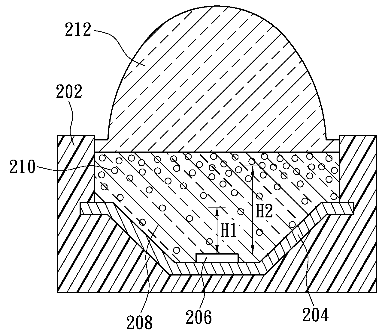
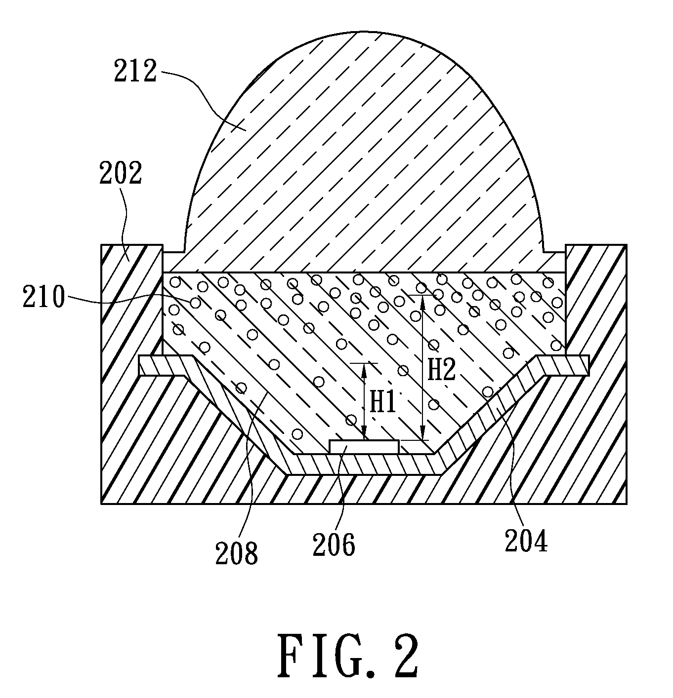
[0019]Please refer to FIG. 2, the present invention discloses a light emitting device and FIG. 2 shows the light emitting device. The light emitting device includes a light emitting body 206, a base 202, an encapsulating material 208, and a wavelength conversion material 210 (i.e. a plurality of fluorescence powders). The base 202 is used for carrying the light emitting body 206, and the encapsulating material 208 covers the light emitting body 206. Furthermore, the wavelength conversion material 210 is mixed into the encapsulating material 208. The concentration of the wavelength conversion material 210 composed of a plurality of fluorescence powders changes according to the distance between the wavelength conversion material 210 and the light emitting body 206 thereby improving the lighting characteristics of the light emitting device. In this embodiment, when the wavelength conversion material 210 is farther away from the light emitting body 206, the concentration of the fluoresc...

second embodiment

[0026]FIG. 3 shows the light emitting device. The light emitting device includes a light emitting body 306, a base 302, an encapsulating material 308, and a wavelength conversion material 310 (i.e. a plurality of fluorescence powders). The base 302 has at least one lead frame 304 which is used for carrying the light emitting body 306, and the wavelength conversion material 310 is mixed into the encapsulating material 308. The mixture of the encapsulating material 308 and the wavelength conversion material 310 covers the light emitting body 306.

[0027]The manufacturing method of the second embodiment has the following steps. First, the light emitting body 306 is assembled on the lead frame 304 of the base 302. Next step is different from the first embodiment. A molding 314 shown in FIG. 3 is assembled on the base 302 and the chamber is defined. Next step is filling the mixture of the encapsulating material 308 and the wavelength conversion material 310 into the chamber defined by mold...

third embodiment

[0030]Please refer to FIG. 4, the light emitting device is shown. The light emitting device includes a light emitting body 406, a base 402, an encapsulating material 408, a wavelength conversion material 410 and a lens 412. The base 402 has at least one lead frame 404 which is used for carrying the light emitting body 406, and the lens 412 has a concave area 4121, i.e., a trench concave down structure. The wavelength conversion material 410 is mixed into the encapsulating material 408. The mixture of the encapsulating material 408 and the wavelength conversion material 410 is filled into the concave area 4121 of the lens 412 or a space defined by the lens 412 with the concave area 4121 and the base 402. The composition of the wavelength conversion material 410 is higher under the condition that the wavelength conversion material 410 are closer to the bottom of the concave area 4121 (i.e. farther away from the light emitting body 406). Furthermore, the wavelength conversion material ...


PUM


Abstract

A light emitting device includes a light emitting body, a base for carrying the light emitting body, an encapsulating material covering the light emitting body and a wavelength conversion material mixing with the encapsulating material. The concentration of wavelength conversion material is characterized by the fact that the concentration of the wavelength conversion material is higher at the higher space that is further from the light emitting body located at the bottom of the light emitting device. Accordingly, the reflection rate of the mixture mixed with the encapsulating material and the wavelength conversion material has gradual variation, and the total reflection on the boundary is reduced thus improves the illumination efficiency.

Description

BACKGROUND OF THE INVENTION[0001]1. Field of the Invention[0002]The present invention relates to a structure of a light emitting device and a manufacturing method thereof. The present invention in particular relates to a light emitting device with high illumination efficiency and a manufacturing method thereof.[0003]2. Description of Related Art[0004]Lighting apparatus sometimes has problems of low illuminating efficiency due to the packaging structure of the lighting apparatus. For solving this problem, particular steps are applied in the manufacturing procedure for increasing the illuminating efficiency.[0005]Please refer to FIG. 1, the structure of a traditional lighting unit is shown. The structure of the traditional lighting unit has a base 102′, a light emitting body 106′, transparent encapsulating material 108′, fluorescence powders 110′ and a lens 112′. The fluorescence powders 110′ are uniformly coated on the interior surface of the lens 112′ by a multi-coating process. The...

Claims


Application Information

Patent Timeline
Patent Type & Authority Applications(United States)
IPC IPC(8): F21V9/08H01L33/50H01L33/56
CPCH01L33/56H01L33/508H01L2224/48091H01L2924/181H01L2924/00014H01L2924/00012
Inventor HSUEH, PAI-SHEN
Owner LITE ON TECH CORP
Why Eureka
Try Eureka