Illuminating optical system for projector

a technology of projectors and optical systems, applied in the field of projector illumination optical systems, can solve the problems of reducing polarization conversion efficiency, and adding new lenses, and achieve the effect of high illumination efficiency

Active Publication Date: 2009-09-10
SHARP NEC DISPLAY SOLUTIONS LTD
View PDF2 Cites 0 Cited by
  • Summary
  • Abstract
  • Description
  • Claims
  • Application Information

AI Technical Summary

Benefits of technology

[0017]An exemplary object of the present invention is to solve the problem described above and to provide an illuminating optical system for a projector with a high illumination efficiency.

Problems solved by technology

The above-described illuminating optical system poses the following problems.
In the polarization converting elements, part of the incident light which falls out of the effective aperture (the aperture defining the range within which polarization conversion is possible) of each polarization converting element does not contribute to polarization conversion, correspondingly reducing polarization conversion efficiency.
However, in the illuminating optical systems having the L-, U-, and S-shaped arrangements, the field lens and the condenser lens have a long synthesizing focal distance, necessarily increasing the focal distance of the first integrator.
The former illuminating optical system thus has reduced polarization conversion efficiency.
However, in this case, the addition of the new lens reduces transmittance and increases costs.

Method used


Image

  • Illuminating optical system for projector
  • Illuminating optical system for projector
  • Illuminating optical system for projector

Examples


first exemplary embodiment

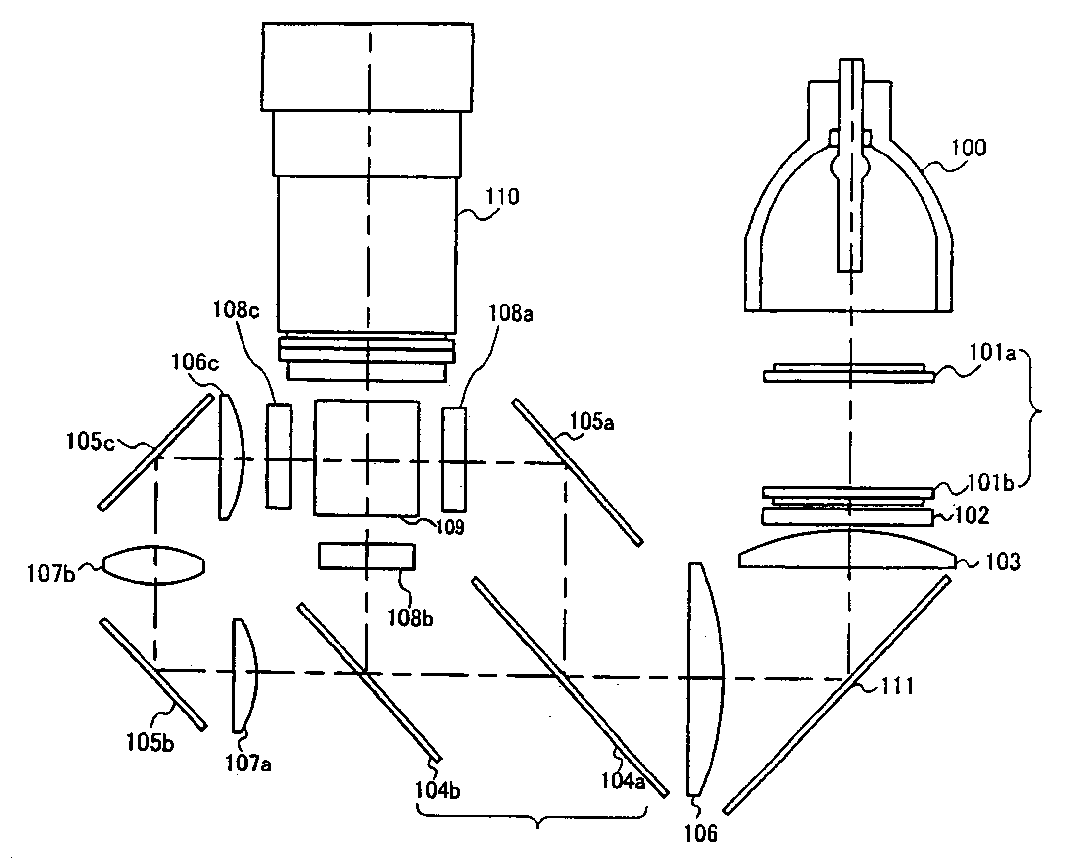
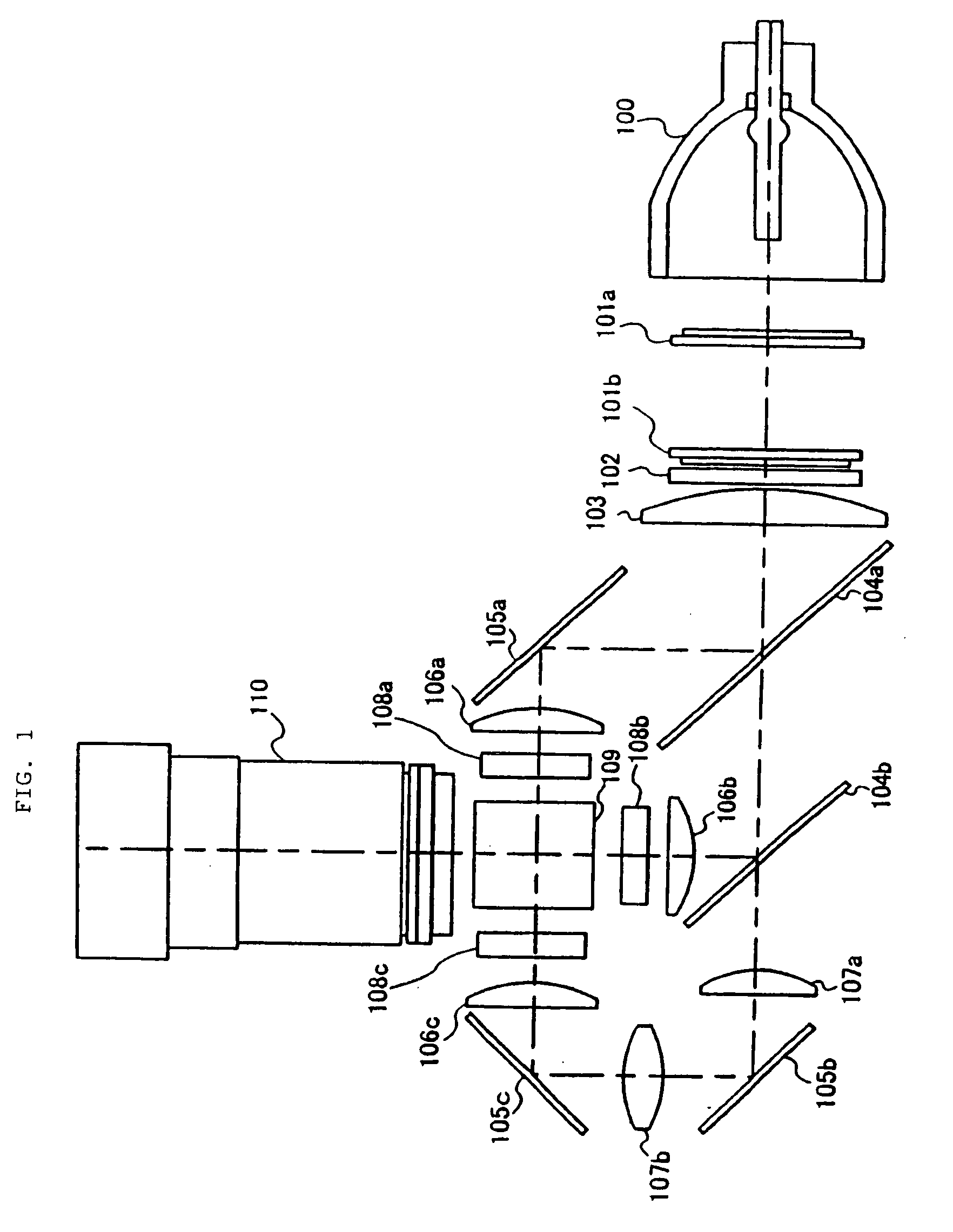
[0088]FIG. 4 shows the configuration of an illuminating optical system for a liquid crystal projector according to a first exemplary embodiment. As shown in FIG. 4, the illuminating optical system according to the exemplary embodiment corresponds to the optical system shown in FIG. 2 and from which condenser lenses 106a and 106b are omitted, with condenser lens 106 located between dichroic mirror 104a and fold-back mirror 111. The optical system is configured to superimposedly irradiate liquid crystal panels 108a and 108b, through field lens 103, with a luminous flux from light source 100 divided by integrator 101a. The arc images of light source 100 are formed on integrator 101b and in the vicinity of integrator 101b by integrator 101a.

[0089]Condenser lens 106 is configured to substantially parallelize principal rays of a luminous flux having passed through field lens 103, located between polarization converting element 102 and fold-back mirror 111. The distance between field lens...

second exemplary embodiment

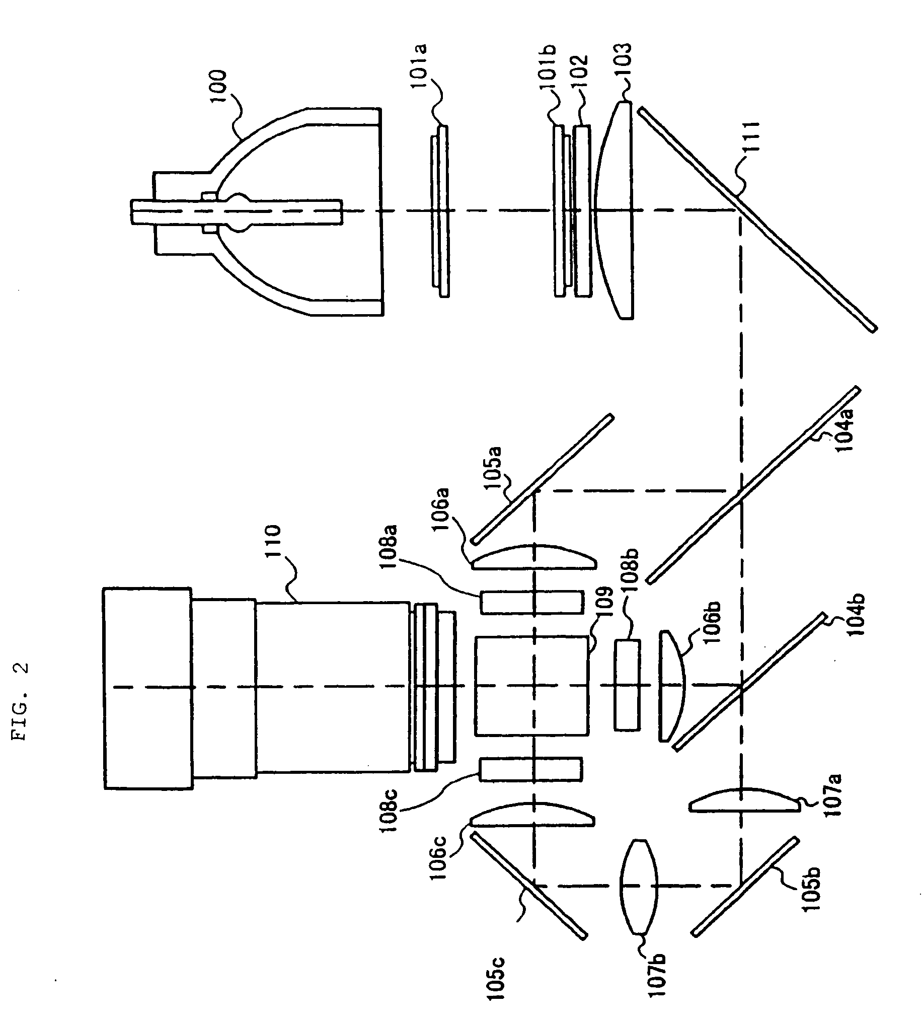
[0094]FIG. 8 shows the configuration of an illuminating optical system for a liquid crystal projector according to a second exemplary embodiment. As shown in FIG. 8, the illuminating optical system according to the exemplary embodiment corresponds to the optical system shown in FIG. 2 and from which condenser lenses 106a and 106b are omitted, with condenser lens 116a located between dichroic mirror 104a and mirror 105a and condenser lens 116b located between dichroic mirrors 104a and 104b. The optical system is configured to superimposedly irradiate liquid crystal panels 108a and 108b with a luminous flux from light source 100 divided by integrator 101a, the luminous flux having passed through field lens 103 and condenser lenses 116a and 116b.

[0095]Each of condenser lenses 116a and 116b is configured to substantially parallelize principal rays of a luminous flux having passed through field lens 103 located between polarization converting element 102 and fold-back mirror 111. The di...

example

[0098]FIG. 9 shows design data on the optical elements of the illuminating optical system shown in FIG. 8. The design data has been calculated using existing optical simulation software. In FIG. 9, “IT1” and “IT2” correspond to integrators 101a and 101b, respectively. “PBS” and “FL” correspond to polarization converting element 102 and field lens 103, respectively. “CL” and “LCD” correspond to condenser lens 116a (or 116b) and liquid crystal panel 108a (or 108b), respectively. A “Radius” column shows the radii of curvature of surfaces of the arranged optical elements (IT1, IT2, PBS, FL, CL, and LCD) in millimeters. “∞” in the “Radius” column denotes a plane. A “Thickness” column shows the thickness of each of the optical elements or the distance between the optical elements in millimeters. An “Index” column shows the refractive index of each of the optical elements. The distance between the optical elements is shown as a linear distance equivalent.

[0099]In the illuminating optical s...


PUM


Abstract

An exemplary aspect of the present invention provides an illuminating optical system for a projector including a light source and a plurality of display panels, the illuminating optical system that includes a first integrator that includes a plurality of lens cells that divide a luminous flux emitted by the light source into a plurality of partial luminous fluxes and that condense the respective partial luminous fluxes, a second integrator that includes a plurality of lens cells on which the respective partial luminous fluxes are incident, a polarization converting element that uniformizes polarizing directions of the luminous fluxes that have passed through the respective lens cells of the second integrator, and color separating unit that separates each of the luminous flux from the polarization converting element into a plurality of color lights of different wavelengths, and wherein a field lens and a condenser lens are arranged between the polarization converting element and the separating unit to superimpose the luminous fluxes that have passed through the respective lens cells of the first integrator, on the plurality of display panels, and the condenser lens is located closer to the color separating means.

Description

BACKGROUND OF THE INVENTION [0001](1) Field of the Invention[0002]The present invention relates to an illuminating optical system for a projector typified by a liquid crystal projector.[0003](2) Description of the Related Art[0004]A known illuminating optical system for a liquid crystal projector comprises an integrator that uniformizes the light intensity of a luminous flux from a light source (Japanese Patent Laid-Open No. 2001-228440 and Japanese Patent Laid-Open No. 2004-045907). The arrangement of optical elements of the illuminating optical system varies. In a known typical arrangement of optical elements, the optical elements are L-, U-, or S-shaped. FIGS. 1, 2, and 3 show examples of an L-shaped arrangement, a U-shaped arrangement, and an S-shaped arrangement.[0005]An illuminating optical system shown in FIG. 1 is for a three-panel liquid crystal projector and illuminates liquid crystal panels 108a to 108c with red light, green light, and blue light, respectively. The illumi...

Claims


Application Information

Patent Timeline
Patent Type & Authority Applications(United States)
IPC IPC(8): G03B21/20G03B21/14
CPCG03B21/20G03B21/208G03B21/2073G03B21/2026
Inventor IWASHITA, TSUTOMU
Owner SHARP NEC DISPLAY SOLUTIONS LTD
Why Eureka
Try Eureka