Illumination optical system and image projection apparatus

an optical system and optical system technology, applied in the direction of picture reproducers, picture reproducers using projection devices, instruments, etc., can solve the problems of loss and reduction of illumination efficiency of illumination optical systems, and achieve high illumination efficiency

Active Publication Date: 2016-09-06
CANON KK
View PDF15 Cites 0 Cited by
  • Summary
  • Abstract
  • Description
  • Claims
  • Application Information

AI Technical Summary

Benefits of technology

[0008]The present invention provides an illumination optical system and an image projection apparatus which has high illumination efficiency.

Problems solved by technology

Thus, the light source image may stick out of (project from) the effective region, resulting in a reduction in the illumination efficiency of the illumination optical system.
Therefore, the effective region is in a rectangular shape, resulting in a loss being likely to occur.

Method used


Image

  • Illumination optical system and image projection apparatus
  • Illumination optical system and image projection apparatus
  • Illumination optical system and image projection apparatus

Examples


embodiment 1

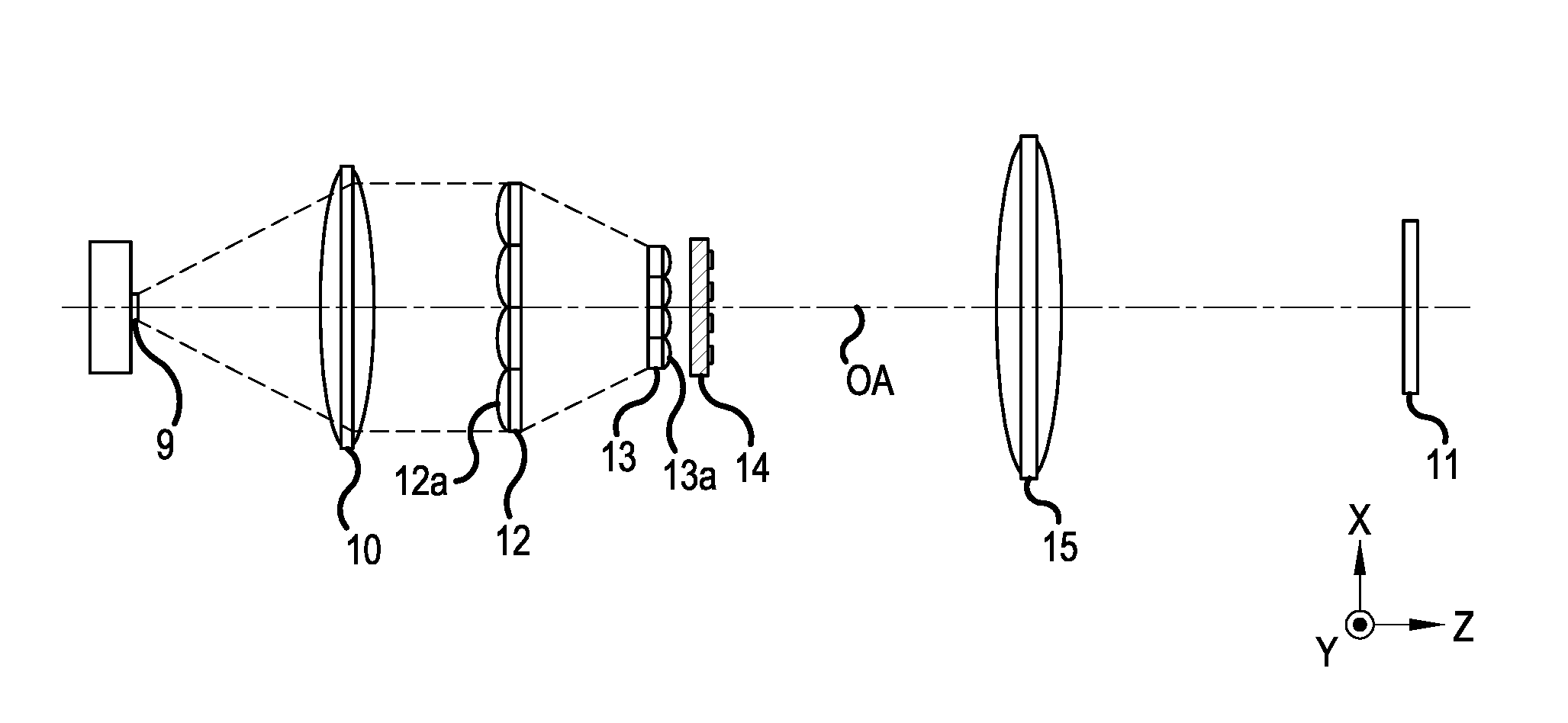
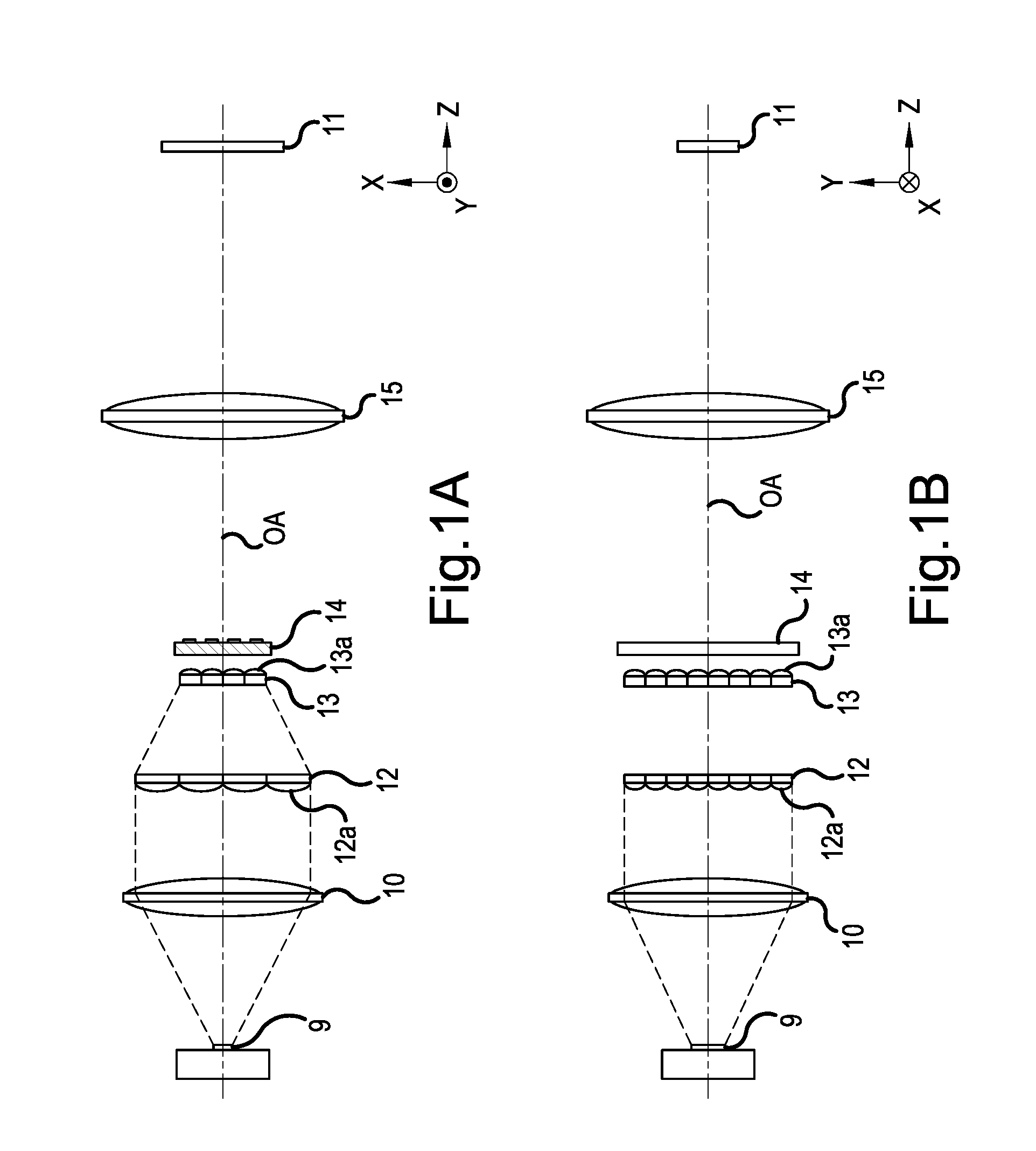
[0029]First of all, referring to FIGS. 1A and 1B, a configuration of an illumination optical system in Embodiment 1 of the present invention will be described. FIGS. 1A and 1B are configuration diagrams of the illumination optical system in the present embodiment, and FIG. 1A illustrates a cross-sectional view when viewed in a Y direction and FIG. 1B illustrates a cross-sectional view when viewed in an X direction. The illumination optical system of the present embodiment is configured such that a diameter of a light beam in a first cross section (an XZ plane) or a second cross section (a YZ plane) can be changed, the cross sections being orthogonal to each other and including an optical axis OA.

[0030]In FIGS. 1A and 1B, reference numeral 9 denotes a light source (a light emitting diode). The light source 9 has a rectangular light emitting surface having an aspect ratio of about 1:2. The aspect ratio is a ratio of a width (a length) in the first cross section (the X direction) to a ...

embodiment 2

[0050]Next, referring to FIGS. 4A and 4B, the configuration of the illumination optical system in Embodiment 2 of the present invention will be described. FIGS. 4A and 4B are configuration diagrams of an illumination optical system in the present embodiment, and FIG. 4A illustrates a cross-sectional view when viewed in the Y direction and FIG. 4B illustrates a cross-sectional view when viewed in the X direction. The illumination optical system of the present embodiment is configured such that the light beam diameter in a first cross section (an XZ plane) or a second cross section (a YZ plane) can be changed, the cross sections being orthogonal to each other and including an optical axis OA.

[0051]In FIGS. 4A and 4B, reference numeral 18 denotes a light source (a light emitting diode). The light source 18 has a rectangular light emitting surface having an aspect ratio of about 2:3. The aspect ratio is a ratio of the width (the length) in the first cross section (the X direction) to th...

embodiment 3

[0067]Next, referring to FIGS. 7A and 7B, a configuration of an illumination optical system in Embodiment 3 of the present invention will be described. FIGS. 7A and 7B are configuration diagrams of the illumination optical system in the present embodiment, and FIG. 7A illustrates a cross-sectional view when viewed in the Y direction and FIG. 7B illustrates a cross-sectional view when viewed in the X direction. The illumination optical system of the present embodiment is configured such that the light beam diameter in a first cross section (an XZ plane) or a second cross section (a YZ plane) can be changed, the cross sections being orthogonal to each other and including an optical axis OA.

[0068]In FIGS. 7A and 7B, reference numeral 25 denotes a light source (a light emitting diode). The light source 25 has a rectangular light emitting surface having an aspect ratio of about 2:3. The aspect ratio is a ratio of the width (the length) in the first cross section (the X direction) to the ...


PUM


Abstract

An illumination optical system is capable of changing a light beam diameter in one of first and second cross sections orthogonal to each other that include an optical axis, and includes a light source, a condenser lens that concentrates light from the light source, a first fly-eye lens including a first lens cell on which light concentrated by the condenser lens is incident, a second fly-eye lens including a second lens cell, a polarization conversion element that performs polarization conversion on light from the second fly-eye lens, and an image display element that displays an image based on light from the polarization conversion element, and widths of the image display element and a light emitting surface of the light source, widths of the first and second fly-eye lens, and change rates α and β of the light beam diameters are set within appropriate ranges.

Description

BACKGROUND OF THE INVENTION[0001]1. Field of the Invention[0002]The present invention relates to an illumination optical system and an image projection apparatus.[0003]2. Description of the Related Art[0004]Conventionally, there have been used illumination optical systems which include a fly-eye lens and a polarization conversion element to uniformly and efficiently illuminate an image display element such as a liquid crystal light valve. In order to increase illumination efficiency in the illumination optical system, an amount of the light beam passing through the effective region formed by the lens cell of the fly-eye lens and the polarization conversion element needs to be increased.[0005]Light source images formed by the illumination optical system are each in a rod shape, which reflects the shape of a discharge arc that is the light source, and are formed to have an inclination according to the position on the reflective surface of a paraboloid reflector through which the light...

Claims


Application Information

Patent Timeline
Patent Type & Authority Patents(United States)
IPC IPC(8): G03B21/20G02B27/09H04N9/31
CPCG03B21/2073G02B27/0961G03B21/208H04N9/3152
Inventor KAWASUMI, TAKEHITO
Owner CANON KK
Why Eureka
Try Eureka