
Rotary shaft locking device and recording apparatus having the same

Active Publication Date: 2009-11-12
SEIKO EPSON CORP
View PDF7 Cites 9 Cited by
  • Summary
  • Abstract
  • Description
  • Claims
  • Application Information

AI Technical Summary

Benefits of technology

[0016]In this aspect, the boss is displaced within the cam groove when the torque transmission member which transmits torque to the rotary shaft is switched between rotation and stop, such that the clutch unit is switched between the unlock state where rotary torque is transmitted to the clutch member (that is, the rotary shaft) and the lock state where the clutch member (rotary shaft) is locked. Therefore, the clutch unit can be configured with a small number of parts and at low cost.
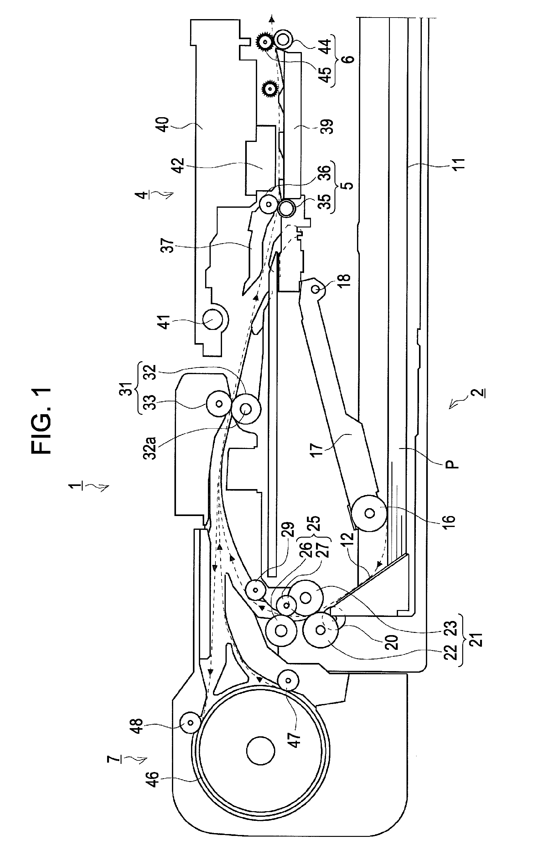
[0018]In this aspect, the second feed roller provided on an upstream side from the first feed roller can rotate forward and backward, and when the rotation direction is switched, can be locked by the locking device according to any one of the first to third aspects of the invention. Therefore, while the recording medium can be transported toward both the upstream side and the downstream side, when the skew removal control using a nip and release method is performed, the backward rotation of the second feed roller can be suppressed. As a result, the skew of the recording medium can be appropriately removed.
[0020]In this aspect, when the first feed roller is switched from backward rotation to forward rotation, the displacement until the first planetary gear returns to the meshed position is set so as to be smaller than the displacement when the second planetary gear is displaced from the unmeshed position to the meshed position. Therefore, after the first feed roller is switched from backward rotation to forward rotation, the second feed roller can rapidly start to rotate forward, without causing a large time lag.
[0021]That is, the first feed roller is driven to rotate backward in a state where the second feed roller has stopped. In this way, after the skew removal control is performed by using the first feed roller and the second feed roller, when the first feed roller is switched to forward rotation again, a time for which the first feed roller rotates forward in a state where the second feed roller has stopped can be shortened. As a result, the recording medium is stretched between the second feed roller and the first feed roller, and thus the recording medium can be prevented from being damaged.
[0025]In contrast, according to this aspect, the leading end of the recording medium returns to the upstream side from the first feed roller by a predetermined amount at the end of the second step, that is, the recording medium is not caught between the first feed roller and the second feed roller. Therefore, when the driving motor is switched to forward rotation subsequent to the second step, not as described above, no tension is applied to the recording medium, and thus recording quality can be prevented from being deteriorated.

Problems solved by technology

However, if the skew removal control is performed for a rigid (hard) sheet, such as a thick sheet or the like, when the leading end of the sheet is released from the downstream roller, a force to rotate the upstream roller becomes large, and in some instances, the upstream roller is rotated backward.
As a result, transport accuracy is degraded, and recording quality is deteriorated.

Method used


Image

  • Rotary shaft locking device and recording apparatus having the same
  • Rotary shaft locking device and recording apparatus having the same
  • Rotary shaft locking device and recording apparatus having the same

Examples


first embodiment

2. First Embodiment of Locking Device

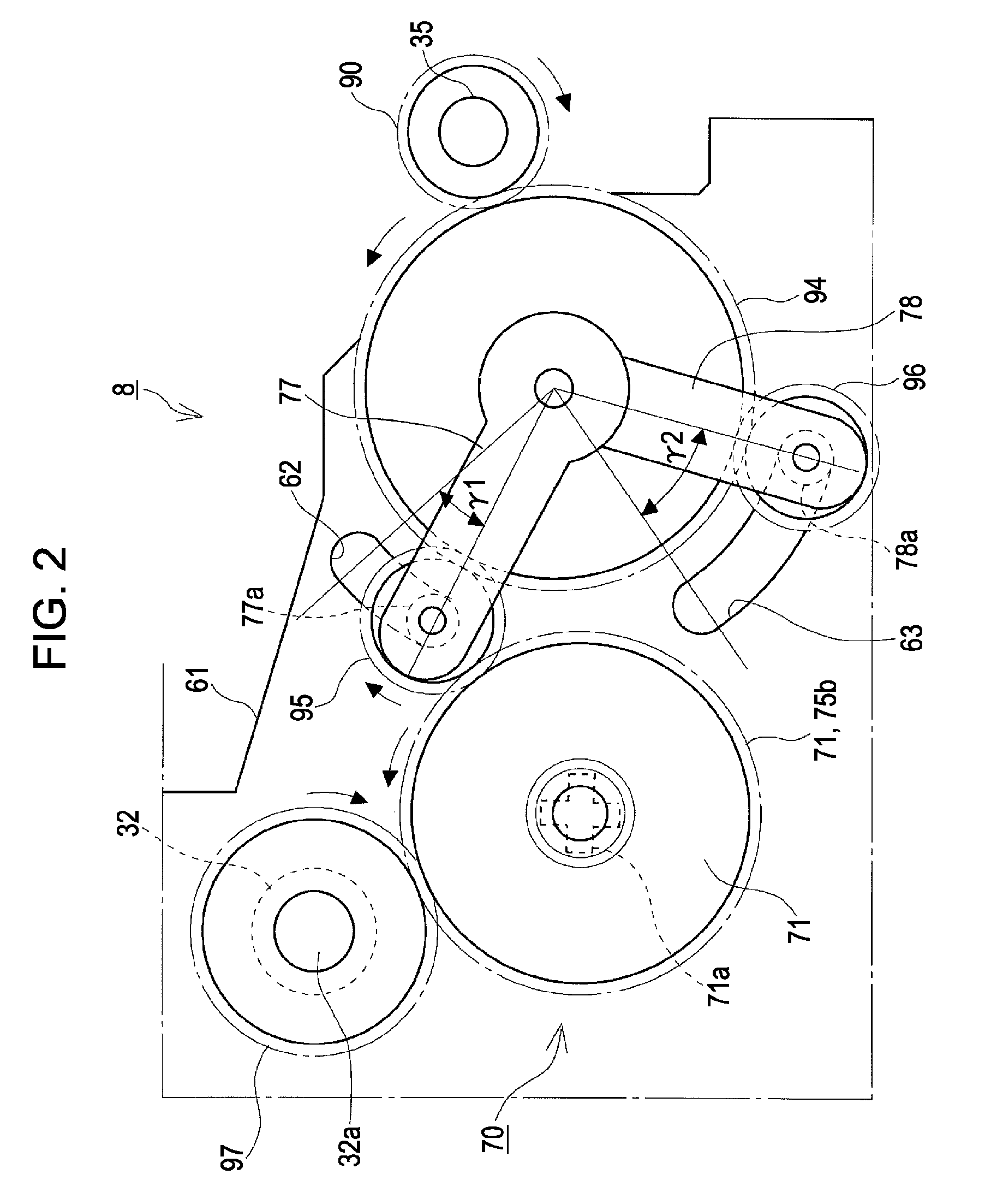
[0061]Hereinafter, a first embodiment of the invention will be described with reference to FIGS. 2 to 8B. In FIG. 2, reference numeral 61 denotes a side frame (constituting the base of the printer 1) forming a plane parallel to a sheet transport direction. The locking device 8 is provided in the side frame 61.

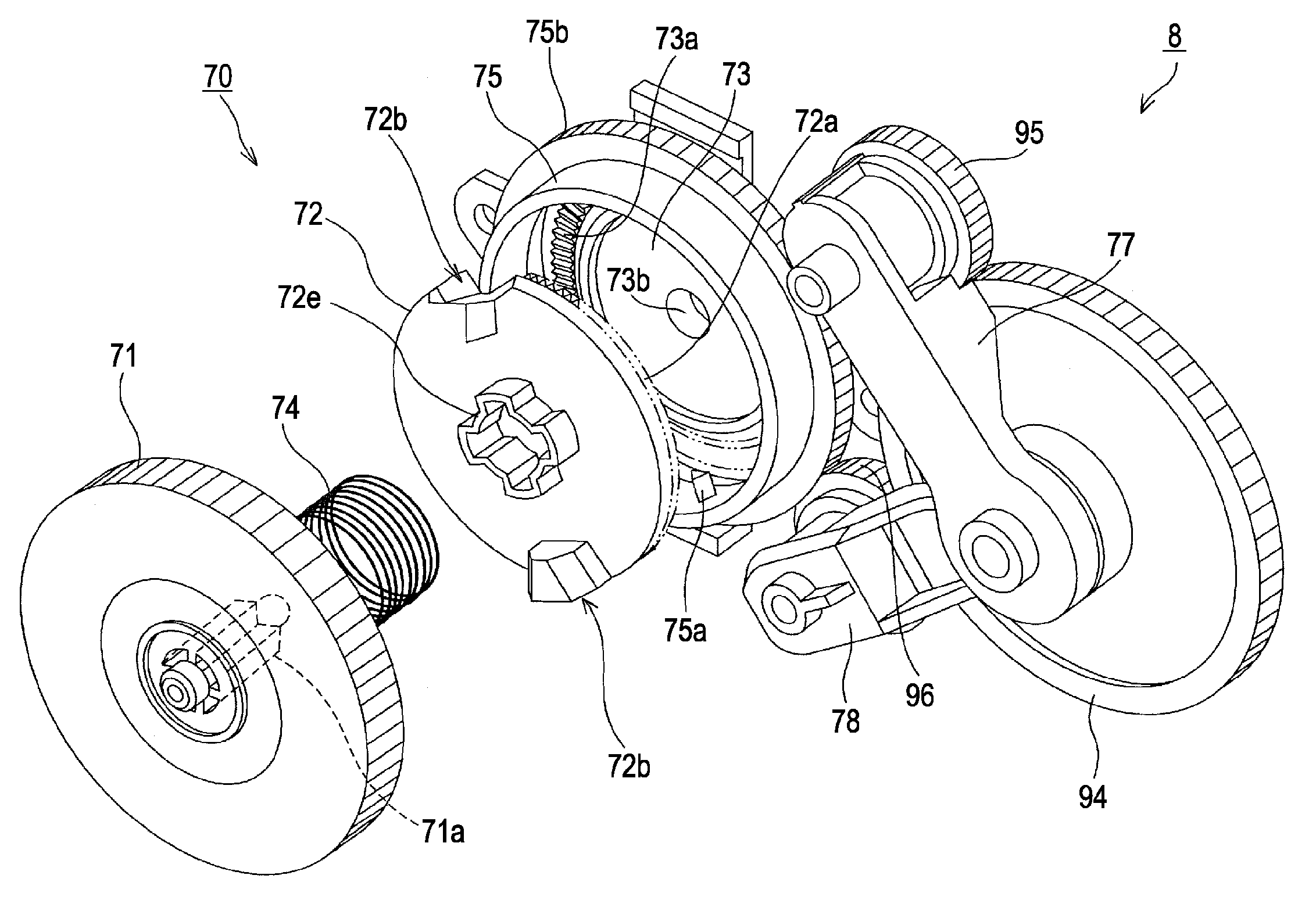
[0062]In FIG. 2, reference numeral 90 denotes a gear that is provided at an axial end of the transport driving roller 35. Rotary torque is transmitted from the gear 90 to the sun gear 94 constituting the locking device 8, and rotary torque is transmitted from the locking unit 70 constituting the locking device 8 to a gear 97. The gear 97 is attached to an axial end of the rotary shaft 32a of the driving roller 32. The locking device 8 is switched between an unlock state where the rotary shaft 32a is permitted to rotate and a lock state where the rotary shaft 32a is regulated to rotate.

[0063]On a left side from the gear 97 of FIG. 2, a gear w...

second embodiment

3. Second Embodiment of Locking Device

[0105]Hereinafter, a locking device 8′ according to a second embodiment of the invention will be described with reference to FIG. 9 to 15B. In FIG. 9, the same constituent elements as those described with reference to FIG. 2 are represented by the same reference numerals, and descriptions thereof will be omitted.

[0106]The locking device 8′ is different from the first embodiment in the position and configuration of the locking unit (represented by reference numeral 50). As shown in FIG. 9, rotary torque of the first planetary gear 95 or the second planetary gear 96 is transmitted to the locking unit 50 through a spur gear 93.

[0107]In FIG. 9, reference numeral 55b denotes a transmission gear corresponding to the transmission gear 75b of the first embodiment. Similarly to the locking unit 70, if the transmission gear 75b receives rotary torque from the first planetary gear 95 or the second planetary gear 96, the locking unit 50 transmits rotary tor...


PUM


Abstract

A rotary shaft locking device includes a locking unit having a transmission gear receiving rotary torque from a power source, transmitting rotary torque to a rotary shaft as the transmission gear receives rotary torque from the power source, and locking the rotary shaft as transmission of rotary torque from the power source is cut off, and a first planetary gear and a second planetary gear provided to be meshed with a sun gear and to planetarily move around the sun gear, and displaced between a meshed position and an unmeshed position so as to be meshed with and separated from the transmission gear. The locking unit locks the rotary shaft for a power cutoff time which occurs when the rotation direction of the sun gear is switched and for which the transmission gear is not meshed with both the first planetary gear and the second planetary gear.

Description

BACKGROUND[0001]1. Technical Field[0002]The present invention relates to a locking device that locks and unlocks a rotary shaft. The present invention also relates to a recording apparatus, such as a facsimile machine or a printer, having the locking device.[0003]2. Related Art[0004]In a recording apparatus, such as a facsimile machine or a printer, as a control method that eliminates a skew (oblique movement) of a sheet, there is known a skew removal control using a “nip and release method”, as described in JP-A-2007-84224.[0005]In the skew removal control, a downstream roller and an upstream roller are used. Specifically, a leading end of a sheet is nipped by the downstream roller, then fed by a predetermined amount to a downstream side, and subsequently released to an upstream side from the downstream roller by backward rotation of the downstream roller while the upstream roller stops. When this happens, the sheet is bent between the upstream roller and the downstream roller, and...

Claims


Application Information

Patent Timeline
IPC IPC(8): B41J11/00F16H57/08
CPCB41J13/0018
Inventor KAWAMURA, SATOSHISHINAGAWA, YUTAKEUCHI, ATSUHIKO
Owner SEIKO EPSON CORP
Learn More